Clamping device for positioning tube socket

A technology of positioning and clamping, tube base, applied in the direction of laser parts, electrical components, lasers, etc., can solve the problems of few tube bases, low production efficiency, complex structure, etc. simple structure

Inactive Publication Date: 2014-11-26
THE 45TH RES INST OF CETC
View PDF3 Cites 0 Cited by
  • Summary
  • Abstract
  • Description
  • Claims
  • Application Information

AI Technical Summary

Problems solved by technology

At present, the clamping method of the tube holder clamp used in the horizontal position on the TO56 infrared semiconductor laser tube base on the production line is mainly realized by pressing the spring-driven clamp into the V-shaped notch on the outer circle of the tube base. Because this kind of fixture needs a set of mechanisms to realize the clamping action, the structure is relatively complicated; in addition, there must be enough space for hand operation, so the number of tube sockets clamped each time is relatively small; in addition, when replacing the tube sockets, it is necessary to It is inconvenient to pull the spring with one hand and change the material with the other hand, which directly leads to low production efficiency

Method used


Image

  • Clamping device for positioning tube socket
  • Clamping device for positioning tube socket
  • Clamping device for positioning tube socket

Examples


Embodiment Construction

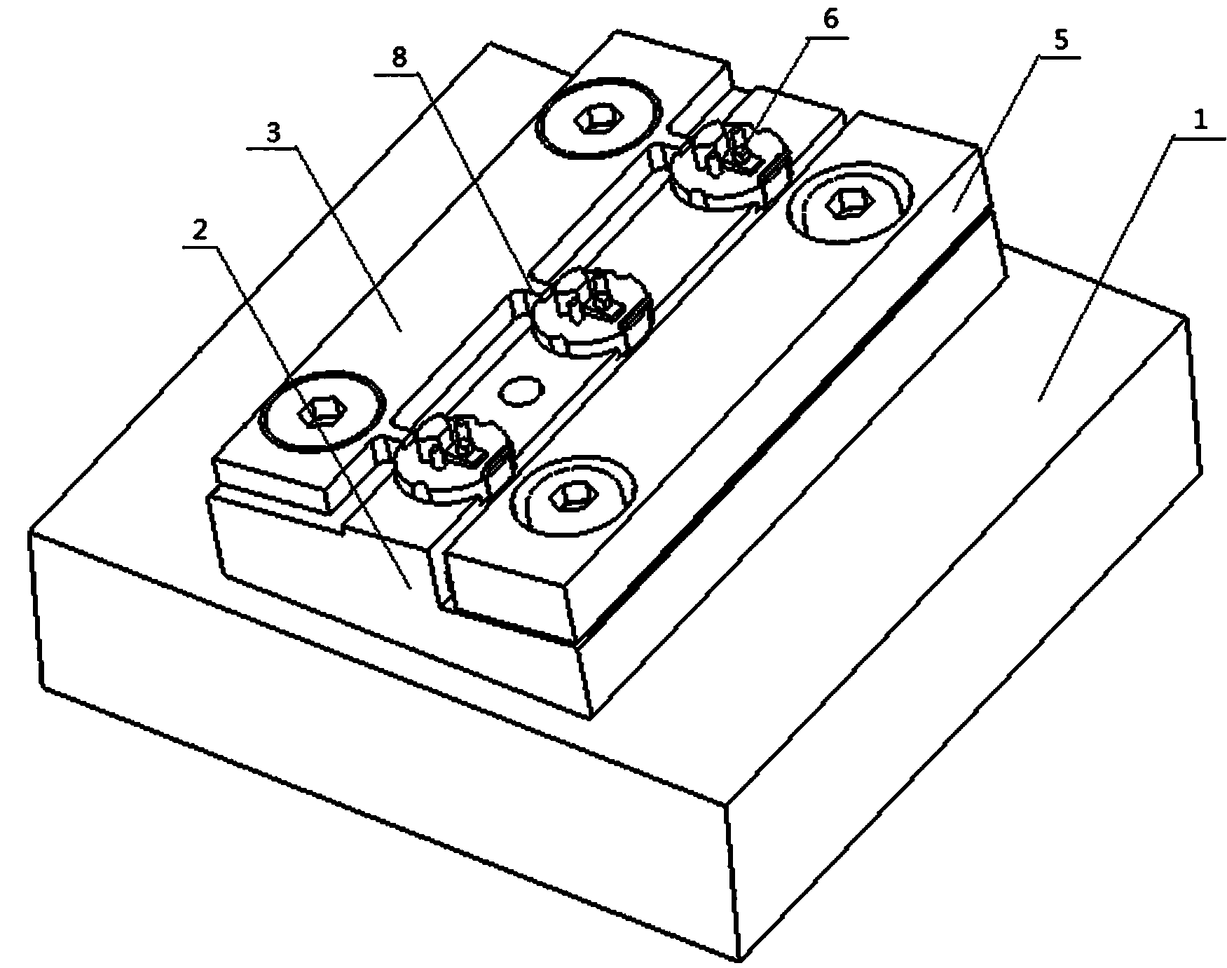
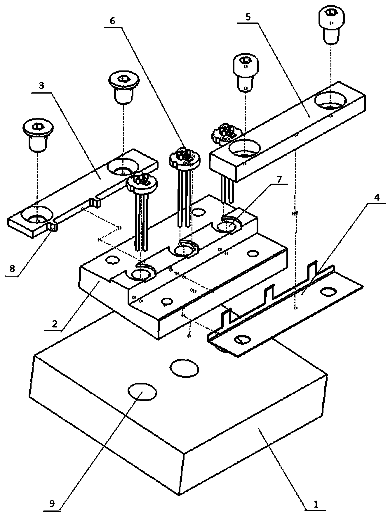
[0013] as attached figure 1 Shown in -4 is a specific embodiment of the present invention, which includes a base 1, a material receiving seat 2 arranged on the base 1, a positioning bar 3 arranged on one side of the material receiving seat 2, and a spring for fixing the spring leaf 4 Compression bar 5, the first round hole 7 for placing the tube base 6 is provided on the material receiving seat 2, and a protrusion for being stuck in the U-shaped groove 12 on the tube base 6 is provided on one side of the positioning bar 3. platform 8, the spring sheet 4 is arranged between the material receiving seat 2 and the pressing strip 5, the base 1 is provided with a second round hole 9 for piercing the tube seat 6, the material receiving seat 2 The lower plane is arranged parallel to the die-bonding platform 10 on the tube base 6 .

[0014] When in use, place the outer circle of the stem 6 of the TO56 infrared semiconductor laser in the first round hole 7 of the material holder 2 of t...


PUM


Abstract

The invention relates to a clamping device for positioning a tube socket, comprising a base, a load support on the base, a positioning bar at one side of the load support and a pressing bar for fixing a spring piece, wherein the load support is provided with a circular hole for placing the tube socket; one side of the positioning bar is provided with a boss for clamping in an U-shaped groove on the tube socket; the spring piece is arranged between the load support and the pressing bar; the base is provided with the circular hole for running through the tube socket; and the lower surface of the load support is parallel to a sticky piece platform on the tube socket. The clamping device is simple in structure and can be used to install the tube socket with one hand, thus the tube socket is replaced quickly and conveniently. The upper and lower surfaces of the load support are parallel to the sticky piece platform on the tube socket, thus ensuring that a chip is pasted on a horizontal plane.

Description

technical field [0001] The invention relates to a tube seat positioning and clamping device, in particular to a device capable of quickly and reliably positioning and clamping a TO56 infrared semiconductor laser tube seat. Background technique [0002] TO56 infrared semiconductor laser is a kind of optoelectronic device, which is widely used in daily life. During the production process of the device, chip bonding needs to be carried out on the horizontal position and the vertical position of the tube base. At present, the clamping method of the tube holder clamp used in the horizontal position on the TO56 infrared semiconductor laser tube base on the production line is mainly realized by pressing the spring-driven clamp into the V-shaped notch on the outer circle of the tube base. Because this kind of fixture needs a set of mechanisms to realize the clamping action, the structure is relatively complicated; in addition, there must be enough space for hand operation, so the n...

Claims


Application Information

Patent Timeline
Patent Type & Authority Patents(China)
IPC IPC(8): H01S5/022
Inventor 郎平任绍彬郭东郝靖周启舟
Owner THE 45TH RES INST OF CETC
Why Eureka
Try Eureka