Vacuum cleaner

A vacuum cleaner and cam technology, which is applied to the wiring structure field of the vacuum cleaner cord reel, can solve the problems of large customer complaints, reduced corporate reputation, uneven winding, etc., and achieves the effect of reducing production costs and enhancing market competitiveness.

Inactive Publication Date: 2011-12-14
LG ELECTRONICS (TIANJIN) APPLIANCES CO LTD
View PDF0 Cites 1 Cited by
  • Summary
  • Abstract
  • Description
  • Claims
  • Application Information

AI Technical Summary

Problems solved by technology

[0006] However, due to the self-weight of the power cord during the return process of the existing cord reel, most of the power cord is piled up at the bottom of the reel when the cord is taken up, resultin

Method used


Image

  • Vacuum cleaner
  • Vacuum cleaner
  • Vacuum cleaner

Examples


Embodiment Construction

[0023] The vacuum cleaner cord reel of the present invention will be further described in detail in conjunction with the accompanying drawings and specific embodiments:

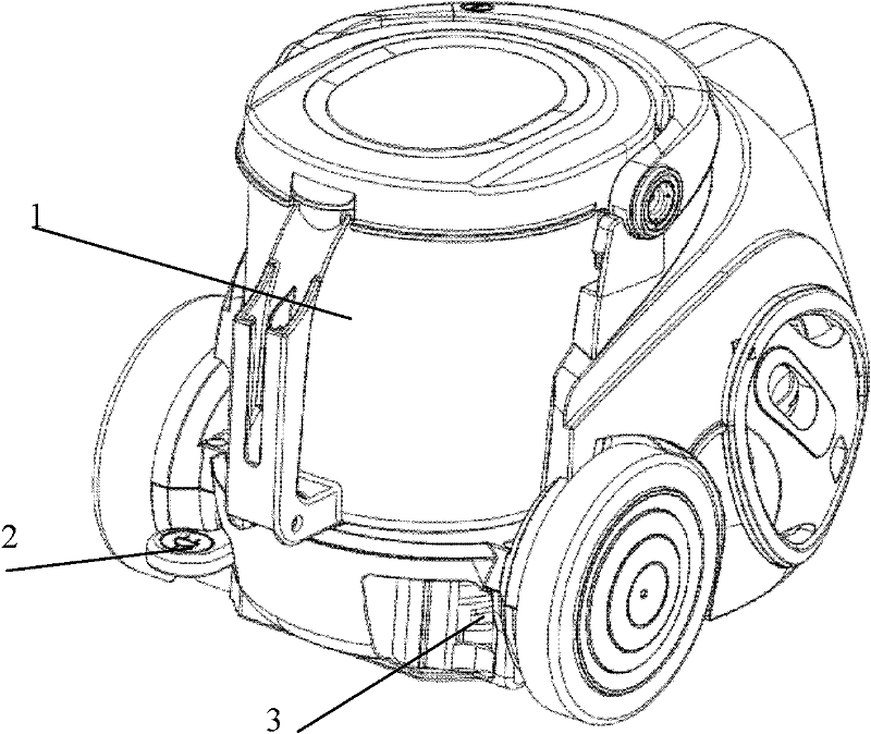
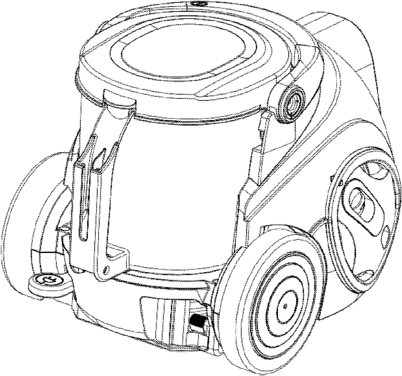
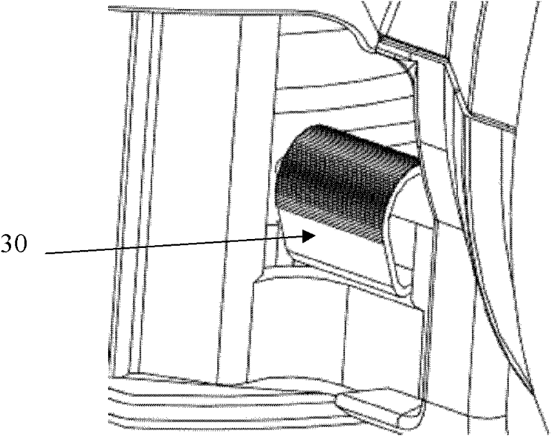
[0024] Such as Figure 2-5 As shown, the vacuum cleaner of the present invention includes a dust collection barrel and a cord reel 20 arranged in the bottom shell of the vacuum cleaner. A power cord 24 is wound around the spool of the cord reel, and a wire inlet 11 that allows the power cord to enter and exit is formed on the body. , the plug of the power cord is limited outside the inlet 11, the plug of the power cord 24 is left at the rear of the back of the bottom case, and the power plug and the power cord can be pulled out during use, and a control coil is provided on one side of the body The cord reel button 21 rotated by the reel, pressing the button 21 can release the restriction on the coil spring, so that the cord reel can be rewound, and a cam structure 30 is rotatably fixed at the entrance 11 of t...


PUM


Abstract

The invention discloses a vacuum cleaner, which includes a dust collecting bucket and a cord reel arranged in the bottom shell of the vacuum cleaner. A line inlet for allowing a power cord to enter and exit is formed on the body of the vacuum cleaner, and the entrance of the power cord is rotatable. The ground is fixed with a cam structure. In the vacuum cleaner of the present invention, a cam structure is added at the wire inlet of the reel, and the rotation of the cam structure realizes the reciprocating movement of the power cord up and down while returning the wire to realize uniform wiring in the height direction, so that the power cord is evenly wound without causing Bottom-side wiring greatly reduces the probability of failures such as non-returning and pulling out of the line; and when using a more material-saving flat power line, there will be no one-sided overlapping phenomenon; the production cost is reduced and the enterprise's reputation is enhanced. Market Competitiveness.

Description

technical field [0001] The invention relates to a vacuum cleaner; in particular, it relates to a wiring structure of a cord reel of the vacuum cleaner. Background technique [0002] Generally, a vacuum cleaner is a device that uses a vacuum to generate suction to inhale air, make the air flow through various filters, filter foreign objects in the air, and clean the room. [0003] Generally speaking, a vacuum cleaner mainly includes a suction device and a suction pipeline. The suction device mainly formed by a motor and a fan is arranged in the body. The suction pipeline includes a suction head and a suction pipe. The suction head has a downward opening. The suction port communicates with the air inlet of the fan inside the body through the telescopic pipe and the flexible pipe of the suction pipe. When the vacuum cleaner is running, the motor drives the impeller of the fan to rotate at a high speed, exhausting the air in the vacuum cleaner, forming an instantaneous vacuum i...

Claims


Application Information

Patent Timeline
IPC IPC(8): A47L9/26
Inventor 岳宏雷任光智
Owner LG ELECTRONICS (TIANJIN) APPLIANCES CO LTD
Why Eureka
Try Eureka