

Sealed Hydraulic Cylinder
A technology for sealing hydraulic pressure and sealing parts, which is applied in the field of hydraulic cylinders and can solve problems such as unreasonable sealing parts and poor sealing performance of oil cylinders
Inactive Publication Date: 2011-12-14
扬州斯普森机械制造有限公司
View PDF0 Cites 6 Cited by
- Summary
- Abstract
- Description
- Claims
- Application Information
AI Technical Summary
Problems solved by technology
[0002] Existing hydraulic cylinders mainly include cylinder barrel, rear end cover, piston, piston rod and seals. Due to unreasonable seals, the sealing performance of the oil cylinder is poor.
Method used
View moreImage
Smart ImageViewing Examples


Examples
Embodiment Construction
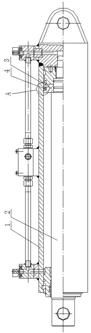
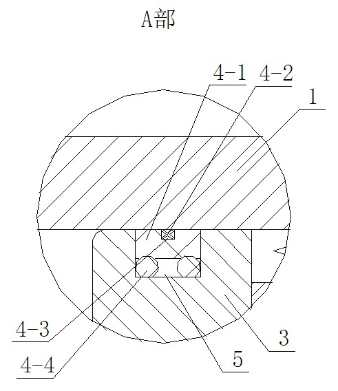
[0008] like figure 1 , 2 As shown, it is a sealed hydraulic cylinder, including a cylinder 1, a piston 3 and a piston rod 2. A seal installation groove 5 is provided on the outer periphery of the piston 3, and a combined seal ring 4 is arranged in the seal installation groove 5. The combined seal ring 4 includes a base Sealing ring 4-1, a star-shaped ring 4-2 and two O-rings 4-4, the outer circumference of the base sealing ring 4-1 is radially provided with a groove 4-3, and the star-shaped ring 4-2 is arranged in the groove In 4-3, two O-rings 4-4 are arranged between the base sealing ring 4-1 and the piston 3 respectively.
Login to View More PUM
 Abstract
A sealed hydraulic cylinder relates to the technical field of hydraulic cylinders, including a cylinder, a piston, and a piston rod. A seal installation groove is arranged on the outer periphery of the piston, and a combined sealing ring is arranged in the seal installation groove. The combined sealing ring includes a base seal ring, a star-shaped ring and two O-rings, grooves are set radially on the outer periphery of the base sealing ring, the star-shaped ring is set in the groove, and two O-rings are respectively set between the base sealing ring and the piston. When the combined sealing ring is installed in the groove, the two O-rings will apply force to the base sealing ring because they are compressed, so that the base sealing ring and the star ring are close to the inner wall of the cylinder to achieve a sealing effect. When the working pressure of the system increases, the pressure acting on the seal is converted into radial pressure, and there is almost no internal leakage of the system.
Description
technical field [0001] The invention relates to the technical field of hydraulic cylinders. Background technique [0002] Existing hydraulic cylinders mainly include a cylinder barrel, a rear end cover, a piston, a piston rod and a seal. Due to unreasonable seals, the sealing performance of the oil cylinder is poor. Contents of the invention [0003] The purpose of the present invention is to overcome the deficiencies of the prior art and provide a sealed hydraulic cylinder with good sealing effect. [0004] The object of the present invention is achieved in this way: a sealed hydraulic cylinder includes a cylinder barrel, a piston and a piston rod, a seal mounting groove is arranged on the outer periphery of the piston, and a combined sealing ring is arranged in the sealing mounting groove, and the combined sealing ring includes a Base sealing ring, a star-shaped ring and two O-rings, the outer circumference of the base sealing ring is radially provided with grooves, the...
Claims
Login to View More Application Information
Patent Timeline
 IPC IPC(8): F16J9/00F16J9/20
Inventor 周华军
Owner 扬州斯普森机械制造有限公司