

Turnplate device and rotary drilling rig
A technology of rotary drilling rig and turntable, which is applied in the directions of rotary drilling rig, support device, rotary drilling, etc., can solve the problem of large load on bolts, and achieve the effect of reducing engineering accidents and prolonging service life.
- Summary
- Abstract
- Description
- Claims
- Application Information
AI Technical Summary
Problems solved by technology
Method used
Image


Examples
Embodiment Construction
[0011] The following will clearly and completely describe the technical solutions in the embodiments of the present invention with reference to the accompanying drawings in the embodiments of the present invention. Obviously, the described embodiments are only some, not all, embodiments of the present invention. Based on the embodiments of the present invention, all other embodiments obtained by persons of ordinary skill in the art without creative efforts fall within the protection scope of the present invention.
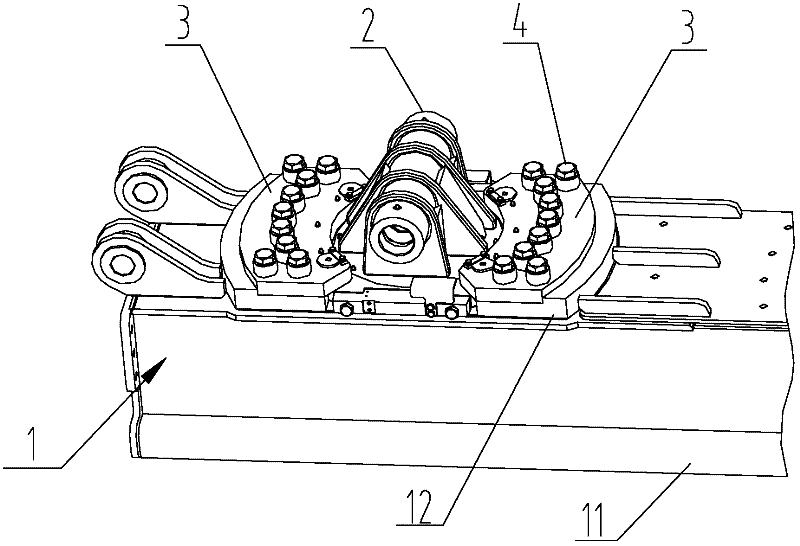
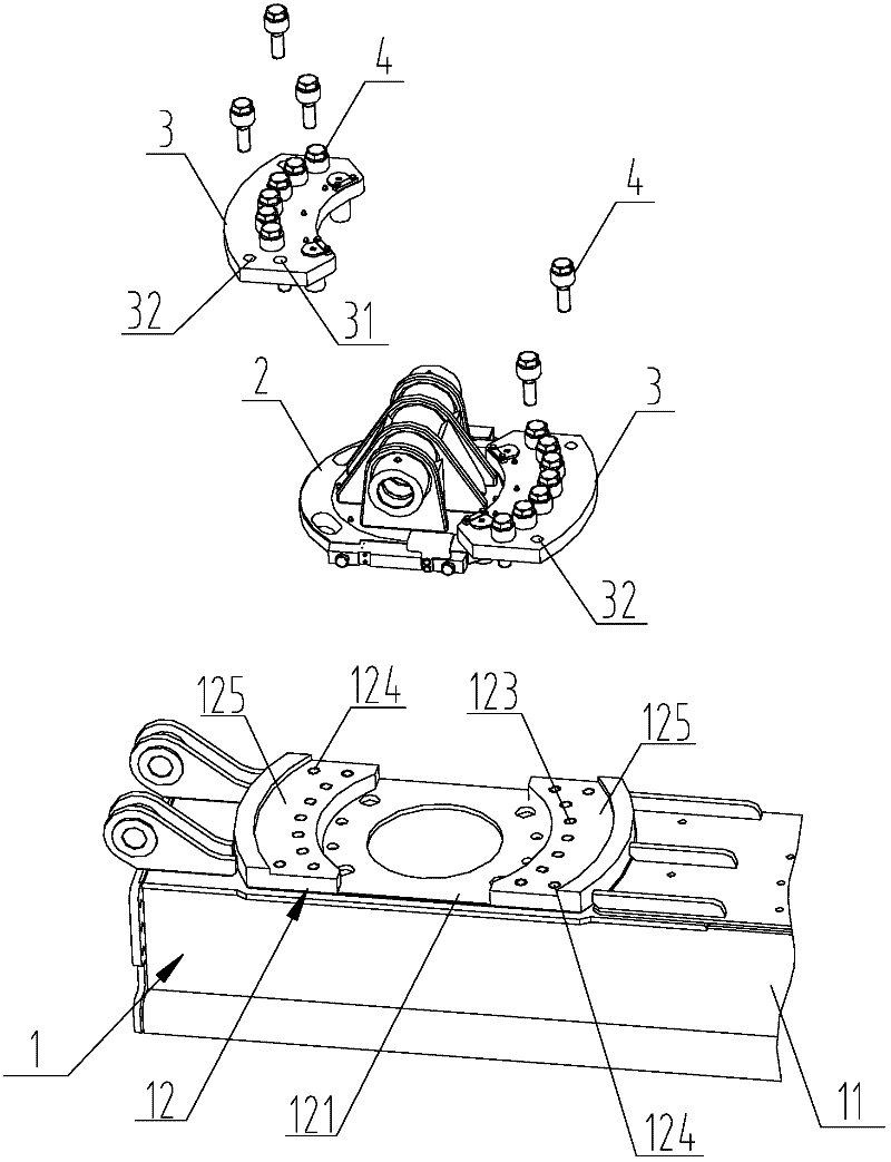
[0012] see figure 1 and figure 2 A preferred embodiment of the present invention provides a rotary table device for a rotary drilling rig, which is applied to the rotary drilling rig. The turntable device includes a mast turntable component 1 , a turntable body 2 , a pressing plate 3 and bolts 4 .
[0013] The mast turntable component 1 is a part of a mast, and the mast turntable component 1 includes a mast part 11 and a turntable connection seat 12 formed on th...
PUM
 Abstract
Description
Claims
Application Information