Vehicl boundary layer air flow control structure

A technology of airflow control and boundary layer, applied in the direction of vehicle components, body, body stability, etc., can solve problems such as turbulence

A technology of airflow control and boundary layer, applied in the direction of vehicle components, body, body stability, etc., can solve problems such as turbulence

CN102470903AActive Publication Date: 2012-05-23NISSAN MOTOR CO LTD

Image

  • Vehicl boundary layer air flow control structure
  • Vehicl boundary layer air flow control structure
  • Vehicl boundary layer air flow control structure

Examples


Embodiment Construction

[0031] Hereinafter, preferred embodiments will be described with reference to the drawings. Those skilled in the art can understand based on the present invention that the following description of the embodiments is for illustration only, and not intended to limit the present invention to the scope defined by the appended claims and their equivalents.

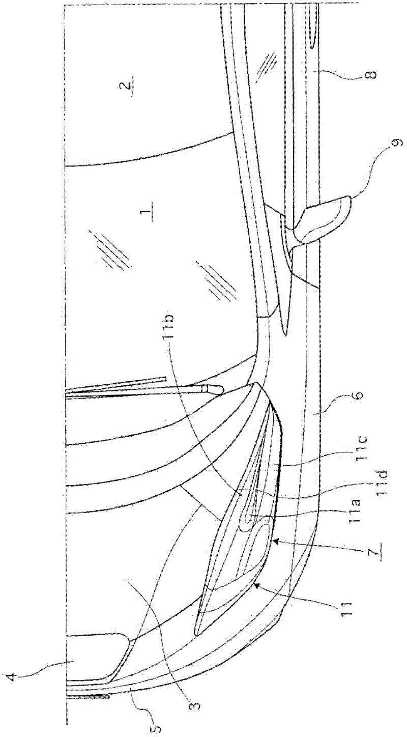
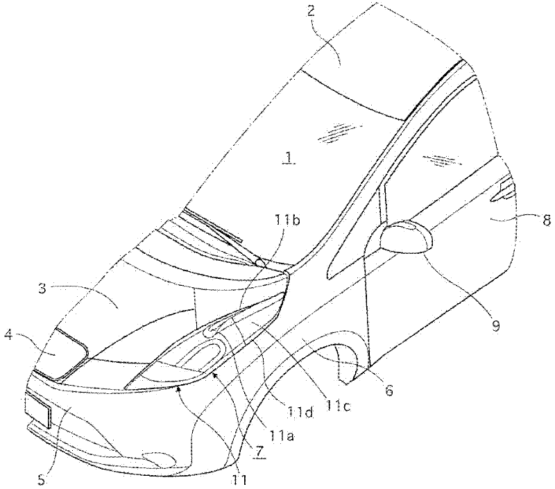
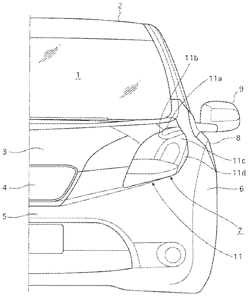
[0032] first reference Figure 1 to Figure 4 , the left front portion of the vehicle body shown is equipped with the vehicle boundary layer airflow control structure for controlling the boundary layer airflow according to the illustrated embodiment. Such as Figure 1 to Figure 4 As shown, the vehicle has a front windshield 1, a car body roof 2, a hood 3 covering the upper opening of the engine room or the motor room, a front grille 4, a front bumper 5, a left front fender 6, and a left headlight 7. Left front door 8 and left side view mirror 9. The term "vehicle body" used herein includes, but is not limited to, the front wi...


PUM


Abstract

A vehicle boundary layer air flow control structure is provided with a vehicle body and a side view mirror (9). The vehicle body includes an exterior contoured surface with an air flow deflector (11). The side view mirror (9) is attached to the vehicle body to provide a diagonally rearward direction to be viewed from a driver's seat. The air flow deflector (11) has a downward air flow guiding surface (11c) provided in a vehicle body region of the exterior contoured surface of the vehicle body along which an air flow heading toward the side view mirror (9) passes. The downward air flow guiding surface extends in an air flow direction of the air flow with respect to the side view mirror (9) to divert the air flow underneath the side view mirror (9).

Description

[0001] Cross application of related applications [0002] This application claims priority to Japanese Patent Application No. 2009-172328 filed on July 23, 2009 and Japanese Patent Application No. 2010-088844 filed on April 7, 2010. The entire disclosures of Japanese Patent Applications No. 2009-172328 and No. 2010-088844 are incorporated herein by reference. technical field [0003] The present invention generally relates to vehicle boundary layer airflow control structures. More particularly, the present invention relates to vehicle boundary layer airflow control structures that advantageously control airflow to body mounted exterior mirrors or other side view mirrors. Background technique [0004] An exterior rear view mirror or other side view mirror is installed on the body of the vehicle so that the driver of the vehicle can see obliquely behind the driver's seat. However, in view of this use, the side mirror inevitably protrudes laterally from the vehicle body. Thu...

Claims


Application Information

Patent Timeline
23 May 2012
Publication
CN102470903A
IPC
B62D35/00; B60Q1/02; B60Q1/04; B60R1/06
CPC
B62D35/00; B60Q1/0017; B62D37/02; B60R1/06
Inventors
小宫哲; 杉本一仁