
Vehicle boundary layer air flow control structure

一种气流控制、边界层的技术,应用在车辆部件、车身、车身稳定等方向,能够解决湍流等问题

Active Publication Date: 2012-05-23
NISSAN MOTOR CO LTD
View PDF8 Cites 2 Cited by
  • Summary
  • Abstract
  • Description
  • Claims
  • Application Information

AI Technical Summary

Problems solved by technology

However, the air flowing along the outer surface of the body may be turbulent due to the shape of the outer surface of the body

Method used


Image

  • Vehicle boundary layer air flow control structure
  • Vehicle boundary layer air flow control structure
  • Vehicle boundary layer air flow control structure

Examples


Embodiment Construction

[0031] Hereinafter, preferred embodiments will be described with reference to the drawings. Those skilled in the art can understand based on the present invention that the following description of the embodiments is for illustration only, and not intended to limit the present invention to the scope defined by the appended claims and their equivalents.

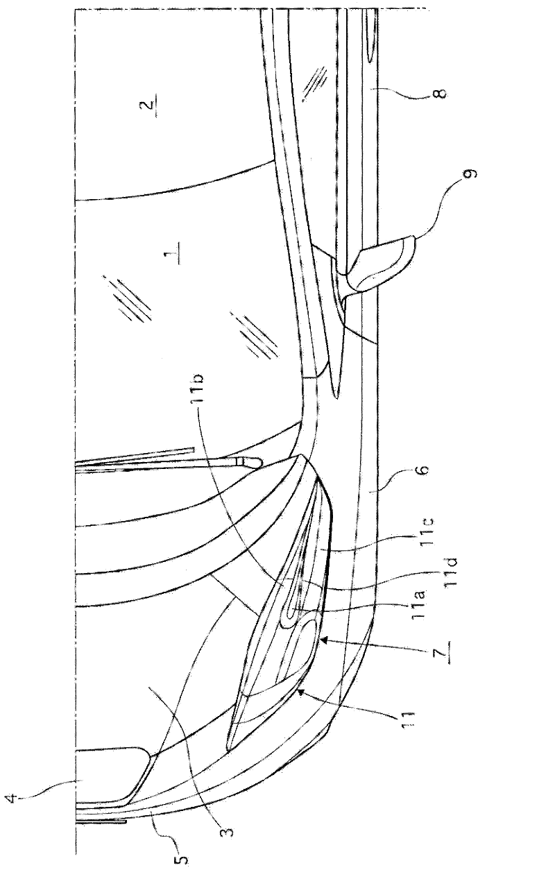
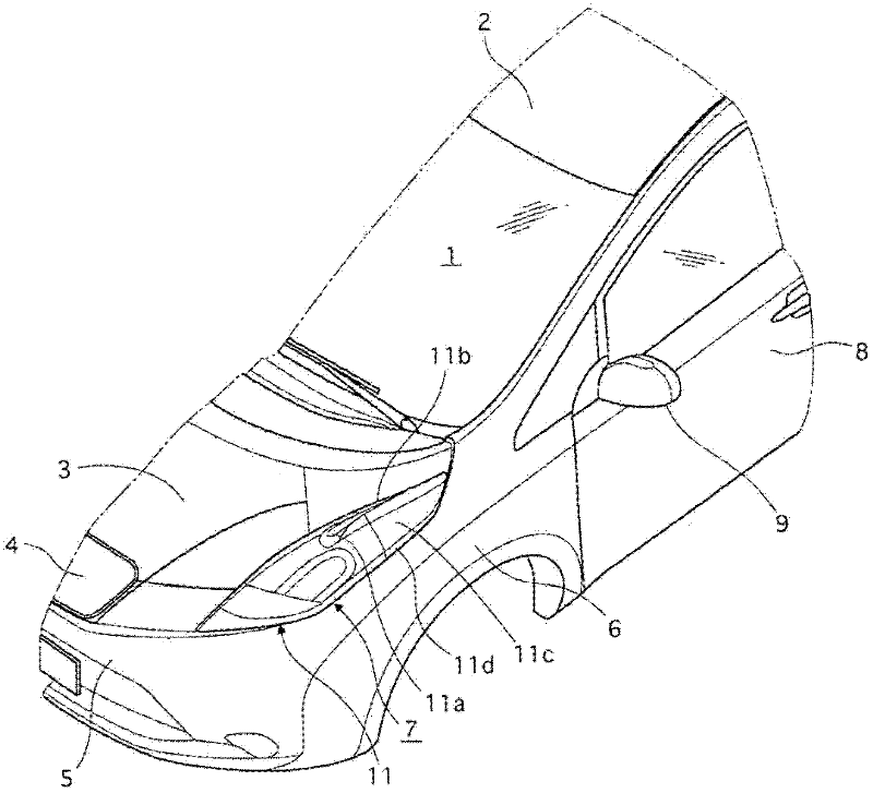
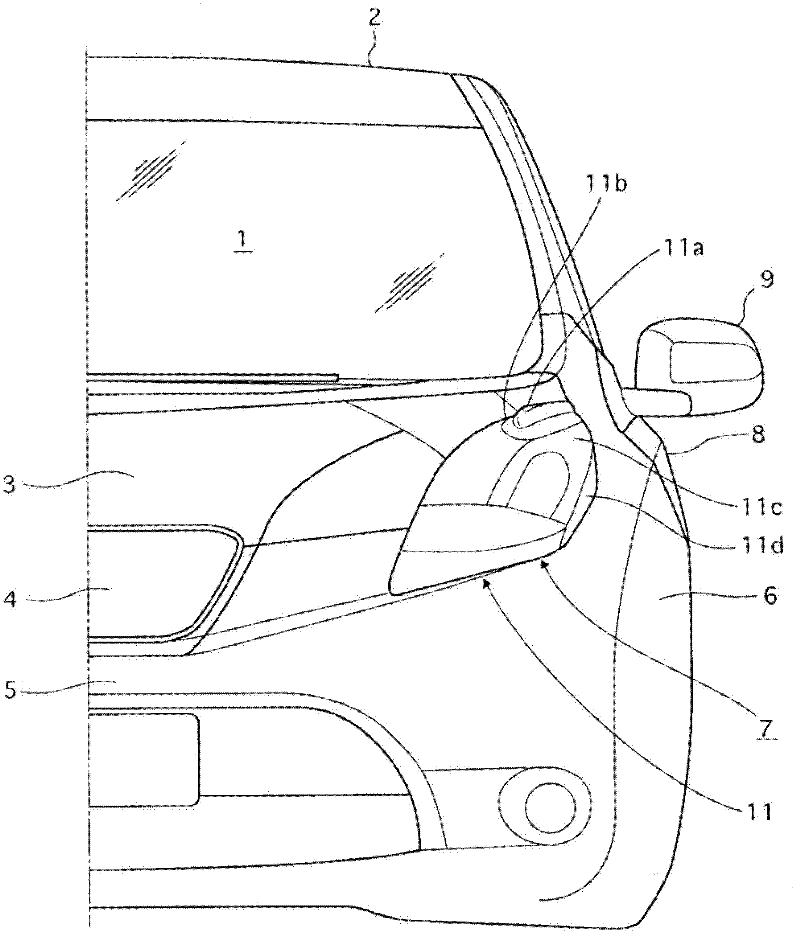
[0032] first reference Figure 1 to Figure 4 , the left front portion of the vehicle body shown is equipped with the vehicle boundary layer airflow control structure for controlling the boundary layer airflow according to the illustrated embodiment. like Figure 1 to Figure 4 As shown, the vehicle has a front windshield 1, a car body roof 2, a hood 3 covering the upper opening of the engine room or the motor room, a front grille 4, a front bumper 5, a left front fender 6, and a left headlight 7. Left front door 8 and left side view mirror 9. The term "vehicle body" used herein includes, but is not limited to, the front winds...


PUM


Abstract

A vehicle boundary layer air flow control structure is provided with a vehicle body and a side view mirror (9). The vehicle body includes an exterior contoured surface with an air flow deflector (11). The side view mirror (9) is attached to the vehicle body to provide a diagonally rearward direction to be viewed from a driver's seat. The air flow deflector (11) has an inward longitudinal air flow guiding surface (11b) provided in a vehicle body region of the exterior contoured surface of the vehicle body along which an air flow heading toward the side view mirror (9) passes. The inward longitudinal air flow guiding surface (11b) extends in an air flow direction of the air flow with respect to the side view mirror (9) to divert the air flow inward of the side view mirror (9) with respect to a vehicle widthwise direction.

Description

[0001] Cross application of related applications [0002] This application claims priority to Japanese Patent Application No. 2009-172330 filed on July 23, 2009 and Japanese Patent Application No. 2010-088849 filed on April 7, 2010. The entire disclosures of Japanese Patent Applications No. 2009-172330 and No. 2010-088849 are incorporated herein by reference. technical field [0003] The present invention generally relates to vehicle boundary layer airflow control structures. More particularly, the present invention relates to vehicle boundary layer airflow control structures that advantageously control airflow to body mounted exterior mirrors or other side view mirrors. Background technique [0004] An exterior rear view mirror or other side view mirror is installed on the body of the vehicle so that the driver of the vehicle can see obliquely behind the driver's seat. However, in view of this use, the side mirror inevitably protrudes laterally from the vehicle body. Thu...

Claims


Application Information

Patent Timeline
Patent Type & Authority Applications(China)
IPC IPC(8): B62D35/00B60Q1/02B60Q1/04B60R1/06
CPCB62D35/00B60Q1/0017B60R1/06B62D37/02
Inventor 小宫哲杉本一仁近藤弘文森仲雅一小屋畑友广井上真人小泉显一郎高木均石原裕二中岛一昭
Owner NISSAN MOTOR CO LTD
Learn More