Centrifugal blower

a centrifugal blower and centrifugal technology, applied in the direction of liquid fuel engines, marine propulsion, vessel construction, etc., can solve the problems of unstable flow, worse wind noise, and airflow disturbance, and achieve the effect of reducing wind nois

Inactive Publication Date: 2007-11-29
SAKAI MASAHARU +2
View PDF8 Cites 17 Cited by
  • Summary
  • Abstract
  • Description
  • Claims
  • Application Information

AI Technical Summary

Benefits of technology

[0009] In view of the foregoing problems, an object of the present invention is to provide a centrifugal blower which can sufficiently reduce the wind noise even when the airflow quantity is small.

Problems solved by technology

As a result, the flow becomes unstable, the airflow tends to be disturbed, and wind noise becomes worse.

Method used


Image

  • Centrifugal blower
  • Centrifugal blower
  • Centrifugal blower

Examples


first embodiment

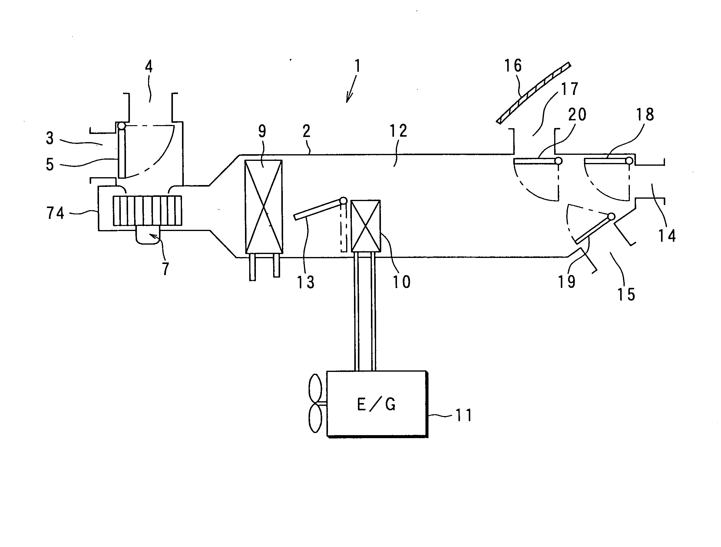
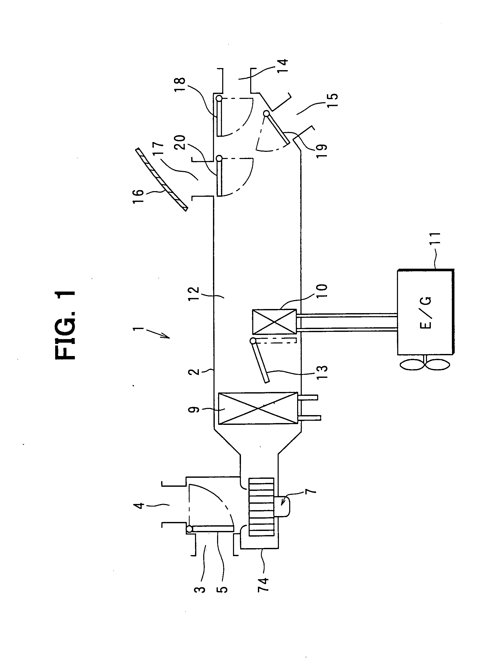
[0053] A centrifugal blower is applied to a blower in a vehicle air-conditioning apparatus according to a first embodiment of the present invention. FIG. 1 is a schematic drawing of a vehicle air-conditioning apparatus 1 for a vehicle equipped with a water-cooled engine, and the centrifugal blower (abbreviated as a blower hereafter) according to the present invention.

[0054] An internal air intake opening 3 for taking in cabin air, and an external air intake opening 4 for taking in outside air are formed on an airflow upstream side of an air conditioner casing 2 forming an airflow passage. An intake-opening switching door 5 is provided for selectively opening and closing the intake openings 3 and 4. Drive means such as a servomotor, or manual operation opens and closes the intake-opening switching door 5.

[0055] A filter (not shown) for removing dust in the air, and a blower 7 according to the present invention are provided on the airflow downstream side of the intake-opening switch...

second embodiment

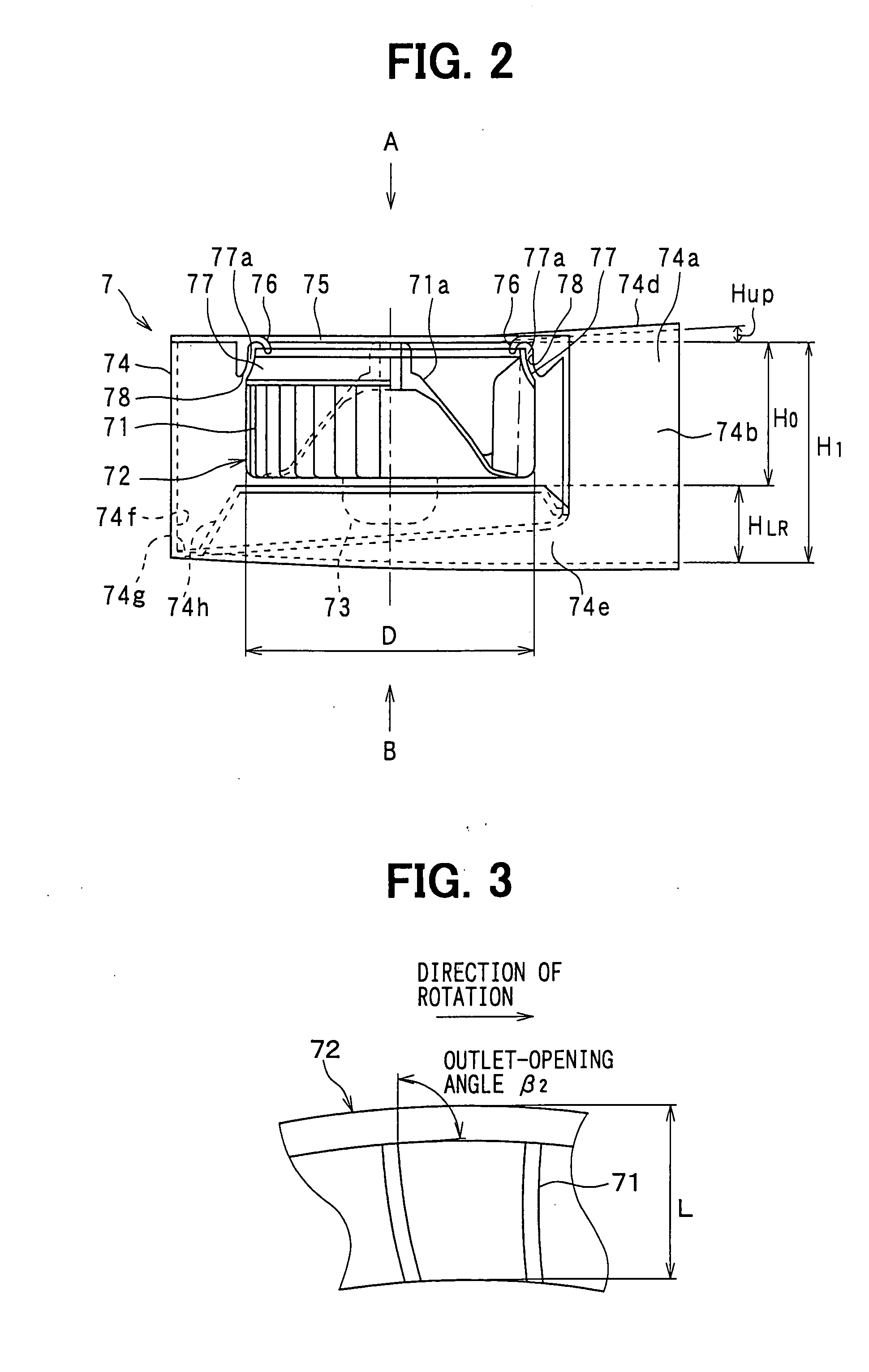
[0085] The cross-section of the flow passage 74a can be set as an approximately rectangular shape whose corners are arcs in a second embodiment as shown in FIG. 11. With this structure, since an unstable swirling flow is prevented from being generated at the corners of the airflow passage 74a, and simultaneously, a generated swirling flow is smoothly circulated, the swirling flow is stabilized, and wind noise is reduced. It is preferable that the curvature radius of the arcs is properly set according to the radius of the swirling flow generated in the airflow passage 74a.

third embodiment

[0086]FIG. 12 shows a third embodiment of the present invention. A protrusion 74j protruding toward the fan 72 is formed along almost the entire airflow passage 74a on the inner wall of the outer peripheral portion of the casing 74, and the cross-section of the protrusion 74j is approximately triangular (wedge-shaped) and protrudes toward the fan 72 when the protrusion 74j is seen from a primary flow direction of the air flowing through the airflow passage 74a.

[0087] With this structure, since the protrusion 74j is provided at a part with which air with the highest flow rate of the air blown out from the fan 72 collides, the air blown out from the fan 72 is easily divided into the side of the inlet opening 75 and the opposite side. This promotes the generation of swirling flow to reduce wind noise generation.


PUM


Abstract

A centrifugal multi-blade fan has multiple blades about a rotational shaft and draws in air along the rotational shaft and then blows the air approximately perpendicular to the rotational shaft to reduce wind noise. A scroll casing encloses the multi-blade fan and defines a scroll-shaped airflow passage for directing the air blown from the multi-blade fan. The scroll casing has an intake opening and an outlet opening at a scroll end, in a downstream scroll casing portion. The scroll casing expands such that a flow passage cross-sectional area on the airflow downstream side is larger than that on an airflow upstream side. A ratio of a blade length to a diameter of the multi-blade fan is greater than or equal to 0.12, and an outer scroll casing radius, relative to the rotational axis, increases as a logarithmic spiral, its expansion angle being from 3.3° to 4.8°.

Description

CROSS REFERENCE TO RELATED APPLICATIONS [0001] This application is a divisional of U.S. patent application Ser. No. 10 / 192,131 filed on Jul. 10, 2002. This application is based upon, claims the benefit of priority of, and incorporates by reference the contents of prior Japanese Patent Applications No. 2001-215649 filed Jul. 16, 2001, and No. 2001-322201 filed Oct. 19, 2001.BACKGROUND OF THE INVENTION [0002] 1. Field of the Invention [0003] The present invention relates to a centrifugal blower having a centrifugal multiblade fan (abbreviated as a centrifugal fan hereafter) applied to a vehicular air-conditioning apparatus. [0004] 2. Description of the Related Art [0005] Generally, centrifugal fans use a centrifugal force to take in air in an axial direction, and to blow the air outward in a radial direction. The air blown out from the centrifugal fan has an airflow of an axial direction component directed from an intake side to a counter-intake side. [0006] In the invention disclosed...

Claims


Application Information

Patent Timeline
Patent Type & Authority Applications(United States)
IPC IPC(8): F01D1/02F04D29/30F04D29/42
CPCF04D29/4233F04D29/30
Inventor SAKAI, MASAHARUMATSUNAGA, KOUJIMITSUISHI, YASUSHI
Owner SAKAI MASAHARU
Why Eureka
Try Eureka