

Device for induction heating
An induction heating device, heating device technology, applied in the direction of induction heating device, induction heating, electric heating device, etc., can solve the problems of impact and wear sensitivity, high price, high heating temperature, etc., to prevent the container from being overheated, preventing oily smoke from igniting, The effect of low thermal inertia
- Summary
- Abstract
- Description
- Claims
- Application Information
AI Technical Summary
Problems solved by technology
Method used
Image

Examples
Embodiment Construction
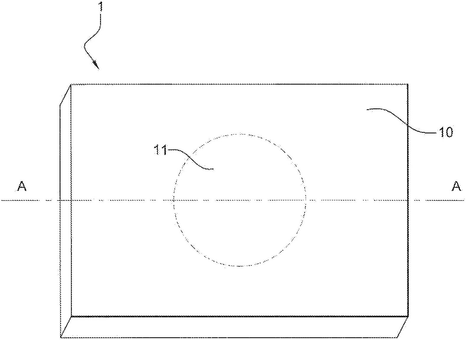
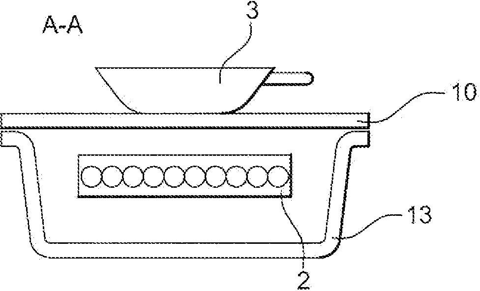
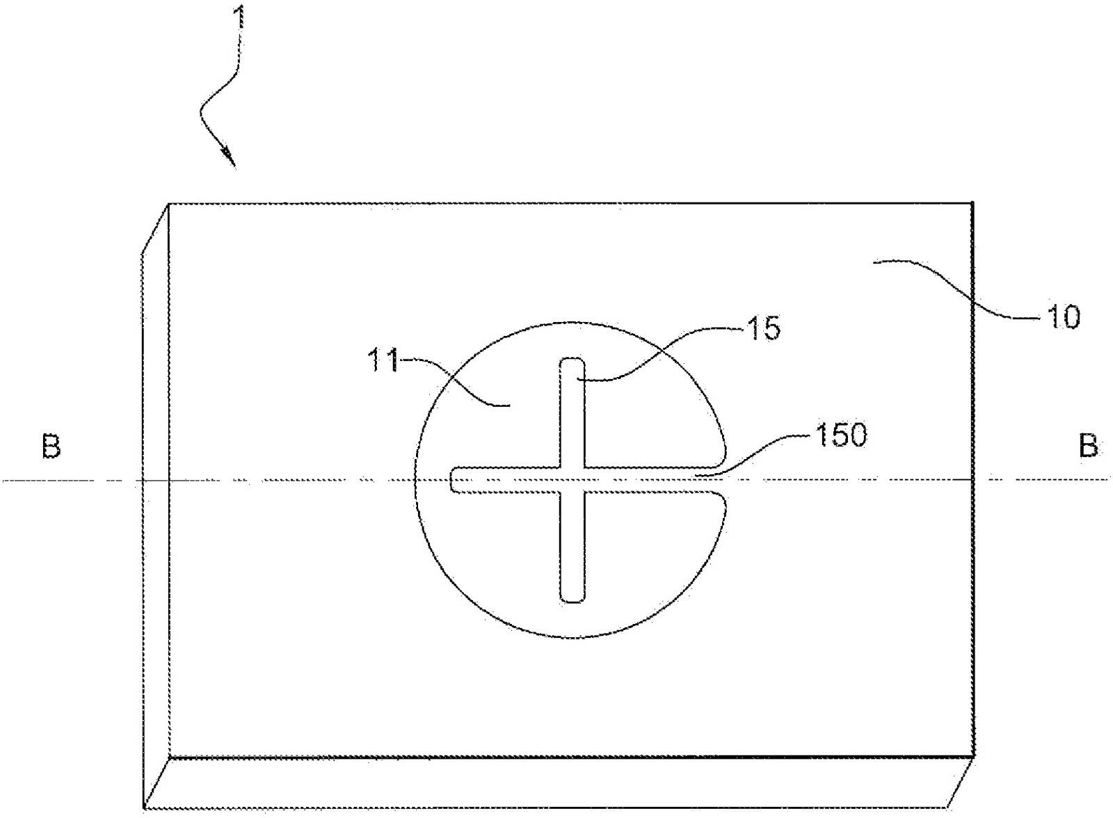
[0082] image 3 , 4 , 5, the induction heating device 1 includes a panel 10 . The face plate 10 has a recess defining a heating zone 11 . A support 15 is placed inside the groove for stably placing the container 3 in the heating zone. The support has a section 150 which contacts the edge of the groove on the panel 10 . A non-magnetic, electrically insulating plate 14 is placed over the groove, extending over the entire surface of the groove, forming the heating zone 11 . The stand rests on a non-magnetic, electrically insulating plate 14 . Encapsulation of panels, supports and non-magnetic electrical insulation panels can be achieved by gaskets or grooves through the chamfered outer edge. There is a groove on the non-magnetic electrical insulating plate 14, and a temperature sensor 4 is arranged in the groove, and its sensing part is in contact with the support 15. An induction coil 2 is placed under the panel 10 and directly opposite to the heating zone 11 .
[0083] T...
PUM
 Abstract
Description
Claims
Application Information