Metal can cap separating mechanism

A separation mechanism, metal can technology, applied in the direction of conveyor objects, transportation and packaging, can solve problems affecting product quality, requirements for product materials, poor separation effect, etc., to achieve high product quality, small occupied space, good separation effect

Active Publication Date: 2012-07-11
YIWU EASY OPEN END INDAL CORP
View PDF6 Cites 10 Cited by
  • Summary
  • Abstract
  • Description
  • Claims
  • Application Information

AI Technical Summary

Problems solved by technology

[0007] The purpose of the present invention is to solve the problems of poor separation effect, requirements on product materials and influence on product quality in the existing metal can lid separation equipment, and to provide a kind of equipment with small footprint, good separation effect, high product quality and Metal can lids of different materials stacked into a cylindrical shape can be separated evenly one by one.

Method used


Image

  • Metal can cap separating mechanism
  • Metal can cap separating mechanism
  • Metal can cap separating mechanism

Examples


Embodiment 1

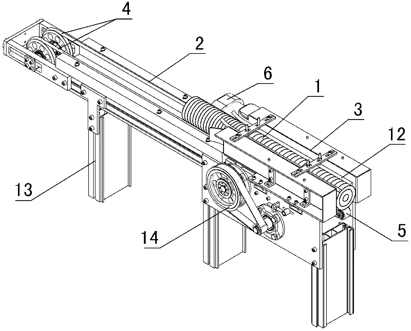
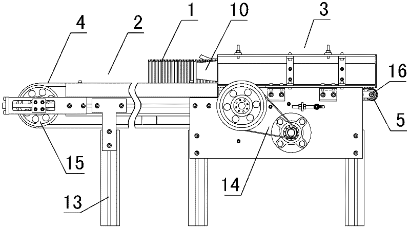
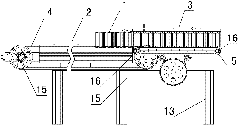
[0027] in such as figure 1 figure 2 In the shown embodiment, a separation mechanism for a metal can lid includes a frame 13 and a can lid separation channel arranged on the frame, and metal can lid limit structures are provided on both sides of the can lid separation channel. The tank cover separation channel comprises a feed channel 2 and a discharge channel 3, the lower part of the feed channel is provided with a feed conveyor belt 4, and the lower part of the discharge channel is provided with a discharge conveyor belt 5, and the feed conveyor belt is two with a cross section of A circular linear conveyor belt, the feed conveyor belt is driven by the feed conveyor wheels 15 arranged at both ends, and its transmission part is symmetrically arranged on the lower part of both sides of the feed channel; the discharge conveyor belt is a rectangular cross-section Ribbon conveyor belt, the discharge conveyor belt is driven by the discharge transmission wheel 16 that is arranged ...

Embodiment 2

[0029] The feeding conveyer belt of embodiment 2 is a strip-shaped conveyer belt with a rectangular cross section, and its conveying part is arranged at the middle position at the bottom of the feed passage. Symmetrically arranged at the lower part of both sides of the discharge channel, the width of the feed conveyor belt is smaller than the interval width between the two discharge conveyor belts, and the moving speed ratio of the discharge conveyor belt and the feed conveyor belt is 10 to 1; the feed channel The center line of the feeding channel is inclined, the height of the center line of the feeding channel decreases gradually along the conveying direction of the metal can cover, and the center line of the discharging channel is horizontally set; the metal can cover anti-dumping devices on both sides of the channel are vacuum devices, so Described vacuum device is arranged on the suction hole on both sides of the channel and the suction mechanism connected with the sucti...


PUM


Abstract

The invention discloses a metal can cap separating mechanism, which comprises a framework, a feeding passage and a discharging passage, wherein the feeding passage and the discharging passage are arranged on the framework. A feeding conveying belt and a discharging conveying belt which are identical in conveying direction and driven by the same power mechanism are arranged below the feeding passage and the discharging passage, the moving speed of the discharging conveying belt is higher than that of the feeding conveying belt, a can cap separating section is arranged between the feeding conveying passage and the discharging conveying passage, the front end of the feeding conveying belt and the rear end of the discharging conveying belt form a staggering structure in the can cap separating section, and metal can cap toppling preventing devices are arranged on two sides of the passage where the discharging conveying belt is located. The metal can cap separating mechanism solves the problem that existing metal can cap separating equipment is poor in separating effect, has requirements for product materials and affection on product quality effectively, is suitable for separation of metal can caps made of different materials and applicable to high-speed production lines of metal can caps.

Description

technical field [0001] The invention relates to a can cover production equipment, in particular to a metal can cover separation mechanism for separating a plurality of stacked or nested metal can covers through a mechanical structure. Background technique [0002] In the production of cans, tea, food and other can packaging products, in the production process of the cans, the production process of the end caps at both ends of the cans is very complicated. The equipment is different, and often needs to be switched during the production process, so each process needs to go through the process of cap feeding, forming, cap output, cap collection and sorting, and then transported to the equipment of the next process. The caps are conveyed piece by piece during the input, forming and output of each process, because the speed of each process cannot be completely matched, so after each process, the caps need to be collected and stacked into a cylinder, and transported to the next p...

Claims


Application Information

Patent Timeline
Patent Type & Authority Applications(China)
IPC IPC(8): B65G47/88
Inventor 骆江波杨春香陈厚忠
Owner YIWU EASY OPEN END INDAL CORP
Why Eureka
Try Eureka