Designing method for cross wedge rolling mould of conical surface stepped shaft part

A technology of die design and step shaft, which is used in metal extrusion forming tools, manufacturing tools, metal processing equipment, etc., can solve problems such as large amount of calculation, difficulty in guaranteeing the accuracy of truncation curves and rolling curves, and inconvenient die design. , to achieve the effect of simplifying design and manufacturing

Inactive Publication Date: 2012-09-26
JILIN UNIV
View PDF4 Cites 9 Cited by
  • Summary
  • Abstract
  • Description
  • Claims
  • Application Information

AI Technical Summary

Problems solved by technology

When the inclination angle of the conical surface is large (greater than 30°), the cross-wedge rolling die with a truncated curve or a truncated curve is currently used for forming. Since the truncated curve or called a rolled curve is a complex spatial curve, Therefore, the calculation amount of cross wedge rolling die design is relatively large, which brings great inconvenience to die design
At the same time, in the mold processing, it is often obtained by manual trimming based on experience, and the accuracy of cutting the curve or rolling the curve is difficult to guarantee.

Method used


Image

  • Designing method for cross wedge rolling mould of conical surface stepped shaft part
  • Designing method for cross wedge rolling mould of conical surface stepped shaft part
  • Designing method for cross wedge rolling mould of conical surface stepped shaft part

Examples


Embodiment

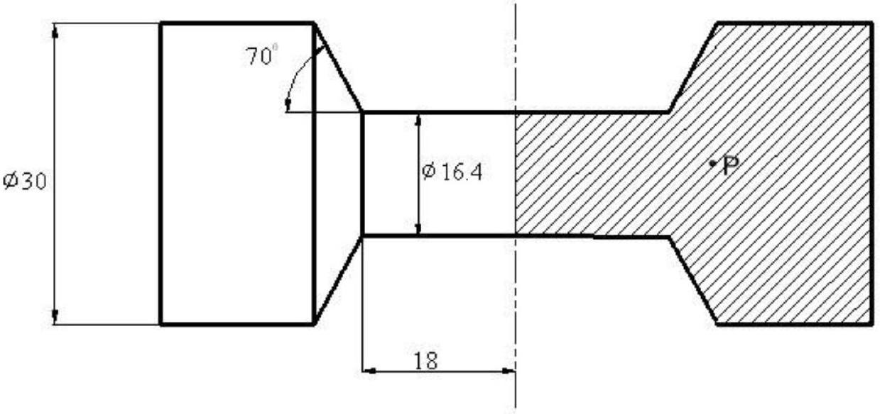
[0104] Using finite element technology to simulate the process of double forming surface method and traditional cross wedge rolling forming tapered step shaft parts respectively in the computer. The parameters of the shaft parts are as follows: the inclination angle of the conical surface step α 1 =70°, the minimum radius r of the conical step shaft 0 =8.2mm, the maximum radius r of conical stepped shaft parts 1 =15mm, widening angle β=8°, half length L of final widening 1 =18mm.

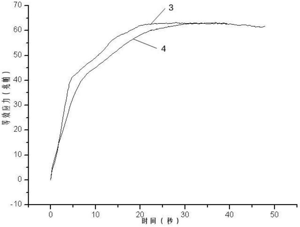
[0105] refer to figure 1 with figure 2 , it can be seen from the figure that the equivalent stress at point P inside the cross-wedge rolling part is smaller than that of the traditional cross-wedge rolling technology before the forming is stable.

[0106] refer to Figure 11 , apply the above-mentioned mold design method to design the mold for the conical step shaft parts. The parameters shown in the figure below take α=30°, α 1 =40°, β=8°, r 1 =16mm, r 0 =8.1mm, l=17.5mm forgings for die...


PUM


Abstract

The invention discloses a designing method for a cross wedge rolling mould of a conical surface stepped shaft part. The designing method comprises the following steps of: 1, designing a structure of the cross wedge rolling mould, wherein the cross wedge rolling mould consists of four parts, namely a wedge section with the length being L, a first widening section with the length being L1, a second widening section with the length being L2 and a shaping section with the length being L3, and the four parts are connected integrally on a template; and the first widening section, the second widening section and the shaping section have the same thickness, and the thickness is equal to a wedge top height (h) of the wedging section; 2, designing the wedging section with the length being L, wherein L=hcot(alpha)cot(beta), h=r1-r0+delta; 3, designing the first widening section with the length being L1, wherein L1=ecot(beta); 4, designing the second widening section with the length being L2, wherein L2=(L1-e)cot(beta); and 5, designing the shaping section with the length being L3.

Description

technical field [0001] The invention relates to a die design method, more precisely, the invention relates to a cross wedge rolling die design method for producing tapered stepped shaft parts. Background technique [0002] The application of stepped shafts in engineering is very extensive, and there are many stepped shafts with conical steps in the stepped shafts; the blank with conical steps is prefabricated by cross wedge rolling forming method for die forging. is common. When the inclination angle of the conical surface is large (greater than 30°), the cross-wedge rolling die with a truncated curve or a truncated curve is currently used for forming. Since the truncated curve or called a rolled curve is a complex spatial curve, Therefore, the calculation amount of cross wedge rolling die design is relatively large, which brings great inconvenience to die design. At the same time, in the mold processing, it is often obtained by manual trimming based on experience, and the...

Claims


Application Information

Patent Timeline
Patent Type & Authority Applications(China)
IPC IPC(8): B21C25/10
Inventor 于鸣王彬乔广金明华
Owner JILIN UNIV
Why Eureka
Try Eureka