Light emitting device and backlight module

A light emitting device and backlight module technology, which is applied in the direction of lighting devices, fixed lighting devices, lighting device components, etc., can solve the problem that the light emitting device is difficult to accurately align the light guide plate, the amount of light incident on the light guide plate is difficult to predict, and the use range of the liquid crystal panel is restricted. limit and other issues

Inactive Publication Date: 2012-10-10
AU OPTRONICS CORP
View PDF5 Cites 8 Cited by
  • Summary
  • Abstract
  • Description
  • Claims
  • Application Information

AI Technical Summary

Problems solved by technology

[0003] In the aforementioned first design structure, it is difficult for the light-emitting device to be precisely aligned with the light guide plate, which makes it difficult to predict the amount of light received by each light guide plate
In the above-mentioned second design structure, although the assembly alignment accuracy between the light emitting device and the light guide plate can be relatively accurately controlled, the incident light of the second light guide plate comes from the first light guide plate, so the amount of incident light obtained by it Difficult to lift, which limits the range of use of the LCD panel corresponding to the second light guide plate
In the aforementioned third design structure, logically two independent liquid crystal display modules are stacked. Although the device alignment accuracy can be relatively accurately controlled and the backlight intensity can be independently controlled, it is obviously difficult to reduce the size of the entire display device.

Method used


Image

  • Light emitting device and backlight module
  • Light emitting device and backlight module
  • Light emitting device and backlight module

Examples


Embodiment Construction

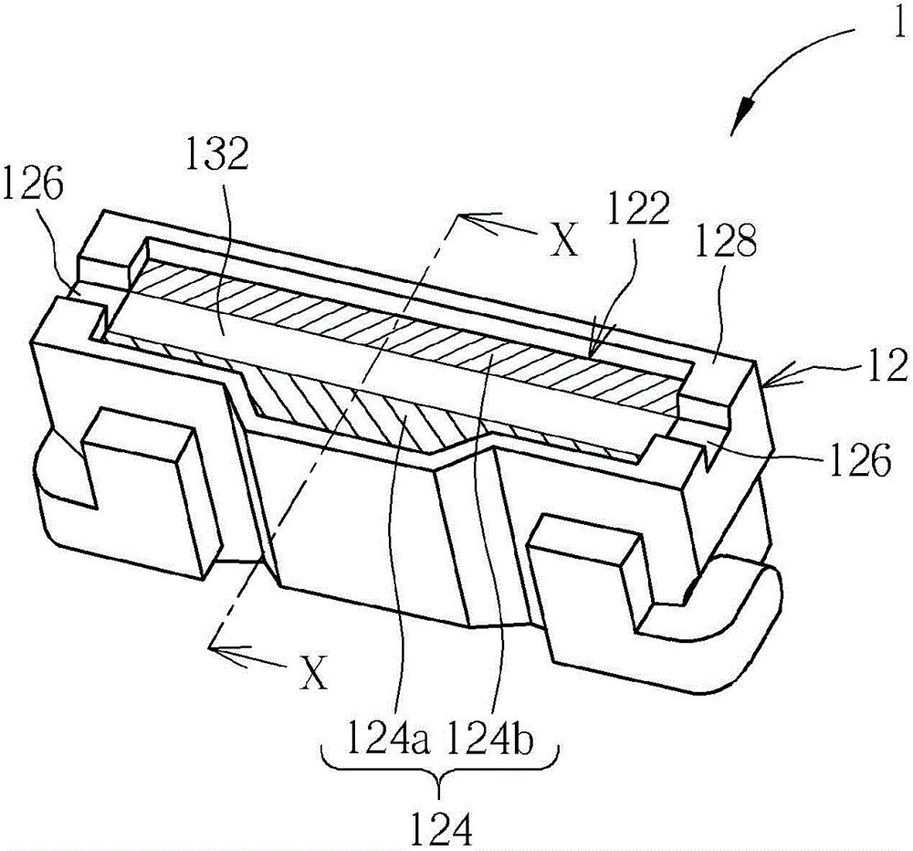
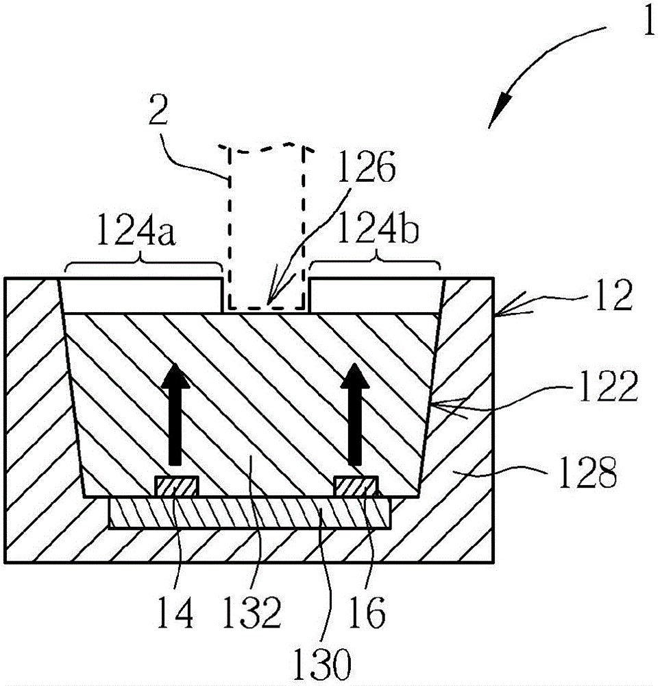
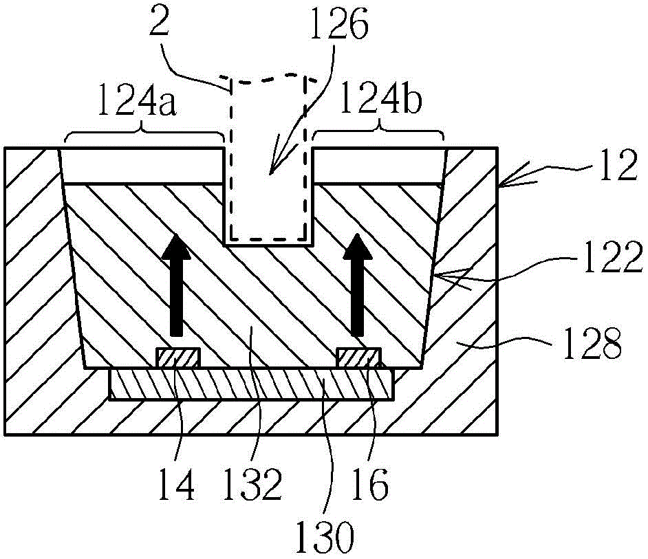
[0019] see figure 1 and figure 2 , figure 1 is a schematic diagram of a light emitting device 1 according to a preferred embodiment of the present invention, figure 2 for figure 1 A cross-sectional view of the middle light-emitting device 1 along the line X-X. The light emitting device 1 includes an insulating carrier 12 , a first light source 14 and a second light source 16 . The insulating carrier 12 has a packaging space 122 and a light-emitting side 124 . A first light exit region 124a and a second light exit region 124b are defined on the light exit side 124 (in figure 1 are indicated by hatching). The insulating carrier 12 includes a positioning groove structure 126 for a reflective sheet 2 (shown in dotted lines in figure 2 Middle) is positioned so that the reflective sheet 2 can separate the first light-emitting area 124a and the second light-emitting area 124b. The first light source 14 is disposed in the packaging space 122 corresponding to the first light...


PUM


Abstract

The invention discloses a light emitting device and a backlight module provided with the light emitting device. The backlight module includes a light guide structure and the light emitting device, the light guide structure includes two light guide members and a reflection sheet arranged between the light guide members. The light emitting device is arranged adjacent to the light guide structure and includes an insulating carrier and two light sources arranged on the insulating carrier. The insulating carrier includes a positioning groove structure, the edge of the reflecting sheet is arranged in the positioning groove structure, the two light sources are respectively corresponding to the two light guide members, and the light emitted by the two light sources can respectively enter into the corresponding light guide members respectively. Therefore, the light emitting device as a single structure can supply the light required by the two light guide member respectively at the same time, and the combination accuracy of the light guide structure and the light emitting device is improved by means of the positioning structure on the light emitting device.

Description

technical field [0001] The invention relates to a light-emitting device and a backlight module, in particular to a light-emitting device capable of providing dual light sources and a backlight module provided with the light-emitting device to provide double backlights. Background technique [0002] With the diversification of consumers' usage habits, display devices that provide front and rear dual screens on a single device structure have come into the market. Generally, the backlight module of dual screens has a design structure that uses a single light emitting device to provide light to two light guide plates at the same time, or uses a single light emitting device to provide light to a light guide plate, and then utilizes a semi-transparent and semi-reflective design to divert the light in the light guide plate Introducing another design structure of the light guide plate, or adopting a design structure in which two light emitting devices respectively correspond to a li...

Claims


Application Information

Patent Timeline
Patent Type & Authority Applications(China)
IPC IPC(8): F21S8/00F21V17/10F21V13/02
CPCG02B6/0068G02B6/0088G02F1/133G02B6/0055G02B6/0001G02B6/0076G02F1/133342
Inventor 林仲文萧予菱谌思廷简元禹
Owner AU OPTRONICS CORP
Why Eureka
Try Eureka