A Conveyor Belt Buffer Chute Withstanding Big Impact

A conveyor belt and large impact technology, applied in the field of buffer chute, can solve problems such as high frequency of replacement, scratches on the conveyor belt, deformation of slide bars, etc., and achieve the effects of convenient maintenance and replacement, reduced gaps, and low impact force

Active Publication Date: 2016-03-30
ANHUI ZHONGYI RUBBER BELTS
View PDF10 Cites 0 Cited by
  • Summary
  • Abstract
  • Description
  • Claims
  • Application Information

AI Technical Summary

Problems solved by technology

The small impact load transfer point generally adopts the way of supporting the conveyor belt with rollers, but in the case of large impact loads, many companies at home and abroad now use a buffer chute composed of a metal frame and wear-resistant slide bars. Among them, the wear-resistant sliding bar is composed of special polymer materials. The advantages are simple structure, convenient installation, easy replacement of the sliding bar, and can withstand the impact of the reprinted material and the friction during the operation of the conveyor belt to a certain extent. The effect of point use is good, but because the impact load points of this product are scattered on different sliders, it is easy to cause local deformation of the slider at some larger impact load points, serious damage, and high frequency of replacement; the polymer engineering on the surface of the slider Although the plastic has good lubricating properties, it is easily broken under the impact load; the deformation of the slide bar causes ore to accumulate at the belt of the chute and between the slide bars, and then scratches the conveyor belt, which not only delays production but also brings a lot of waste

Method used


Image

  • A Conveyor Belt Buffer Chute Withstanding Big Impact
  • A Conveyor Belt Buffer Chute Withstanding Big Impact

Examples


Embodiment Construction

[0010] The present invention will be further described below in conjunction with the accompanying drawings.

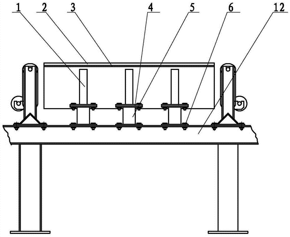
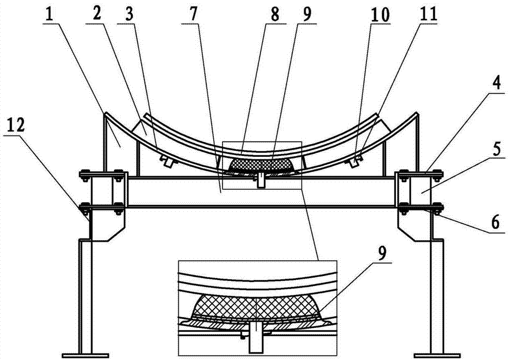
[0011] like figure 1 , 2 As shown, the present invention includes a buffer bracket 1, a conveyor longitudinal beam 12, a buffer slide plate 2, an arc-shaped steel plate 3, a rubber spring 5, a conveyor beam 7, and the like. The upper surface of the buffer bracket 1 is concave arc-shaped, and the arc-shaped steel plate 3 is placed, and the two are welded as a whole; the buffer slide 2 is provided with a skateboard skeleton 9 inside, and the skateboard mounting ear 10 is welded in the middle of the skateboard skeleton 9; The buffer slide plate 2 is 3-4 pieces, arranged on the top of the arc steel plate 3, the slide plate mounting ear 10 is inserted into the hole reserved by the arc steel plate 3, and fixed with a wedge-shaped mounting block 11 on the bottom surface of the arc steel plate 3; Place conveyer belt 8 above slide plate 2.

[0012] The rubber spring 5 is ins...


PUM


Abstract

The invention discloses a conveying belt buffering chute capable of bearing large impact, and solves the problems of partial deformation, serious damage and greatly high change frequency of a slider, which are easy to occur when the conventional buffering chute bears large impact load. The conveying belt buffering chute is characterized by comprising buffering sliding plates, an arc steel plate and rubber springs, wherein the arc steel plate is arranged on a buffering bracket; the 3-4 buffering sliding plates are arranged on the arc steel plate and are internally provided with sliding plate frameworks; sliding plate installation lugs are arranged in the middle of the sliding plate frameworks, are inserted into performed holes in the sliding plate installation lugs and are fixed on the bottom surface of the arc steel plate by wedge-shaped installation blocks; and the rubber springs are arranged between upper spring installation supports and lower spring installation supports. The conveying belt buffering chute can continuously bear large impact load without deformation, is rapid and convenient to install and convenient to maintain, has a long service life, can save maintenance costs and improve production efficiency, and can be widely applied to enterprises of mining, benefication and the like with high impact transfer points.

Description

technical field [0001] The invention relates to a conveying device, more specifically to a buffer chute for a transfer point of a belt conveyor. Background technique [0002] Buffer chutes are used for belt support at the loading point of belt conveyors. The small impact load transfer point generally adopts the way of supporting the conveyor belt with rollers, but in the case of large impact loads, many companies at home and abroad now use a buffer chute composed of a metal frame and wear-resistant slide bars. Among them, the wear-resistant sliding bar is composed of special polymer materials. The advantages are simple structure, convenient installation, easy replacement of the sliding bar, and can withstand the impact of the reprinted material and the friction during the operation of the conveyor belt to a certain extent. The effect of point use is good, but because the impact load points of this product are scattered on different sliders, it is easy to cause local deforma...

Claims


Application Information

Patent Timeline
Patent Type & Authority Patents(China)
IPC IPC(8): B65G15/60
Inventor 宋长江马险峰
Owner ANHUI ZHONGYI RUBBER BELTS
Why Eureka
Try Eureka