A light-emitting device and related light source system

A light-emitting device and light-emitting element technology, applied in the field of lighting and display, can solve the problems of high cost, difficult process, unfavorable heat dissipation of LED lamps, etc., and achieve the effect of improving uniformity

Active Publication Date: 2016-06-01
YLX INC
View PDF4 Cites 0 Cited by
  • Summary
  • Abstract
  • Description
  • Claims
  • Application Information

AI Technical Summary

Problems solved by technology

However, the cost of using a multi-layer PCB board is high, and the thermal resistance is large, which is not conducive to the heat dissipation of the LED lamp, and the process is difficult

Method used


Image

  • A light-emitting device and related light source system
  • A light-emitting device and related light source system
  • A light-emitting device and related light source system

Examples


Embodiment 1

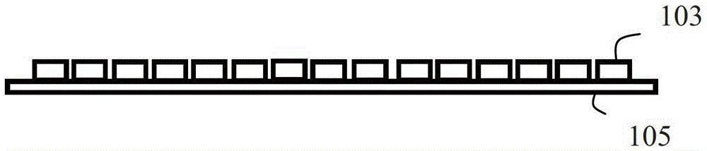
[0032] see Figure 2A , Figure 2A It is a structural schematic diagram of an embodiment of the light emitting device in the embodiment of the present invention. Such as Figure 2A As shown, the light emitting device includes a PCB board 105 and a light emitting element group 103 arranged on one side of the PCB board 105 . The light-emitting element group includes light-emitting elements of two different colors. In this embodiment, the light-emitting elements of two different colors are blue LEDs and yellow LEDs.

[0033] Such as Figure 2B as shown, Figure 2B yes Figure 2A A schematic diagram of the arrangement of the light-emitting element groups in the light-emitting device shown. The light-emitting element group 103 is formed by at least two strings of light-emitting elements. In this embodiment, each string of light-emitting elements on the PCB is arranged in a straight line, and different strings are arranged in parallel to form an array. Wherein the same string...

Embodiment 3

[0064] see Figure 11 , Figure 11 It is a schematic diagram of another embodiment of the light emitting device in the embodiment of the present invention. Different from the above embodiments, in this embodiment, the light-emitting element groups of the PCB board are arranged in multiple concentric rings, wherein each ring is a string of LEDs. Compared with the above embodiments, the arrangement of the light-emitting element groups in this embodiment makes the light beam emitted by the light-emitting device circular, so as to better match the shape of the lens.

[0065] Preferably, among the light emitting elements located on the same circle, at least part of any adjacent two light emitting elements have different colors.

[0066] It is easy to understand that, in this embodiment, the light-emitting element groups of the PCB board may not be arranged in a plurality of concentric rings, but in a plurality of concentric polygons, wherein each polygon is a string of LEDs, whic...


PUM


Abstract

The embodiment of the present invention discloses a light-emitting device, which includes a PCB board and a light-emitting element group on the PCB. The at least part of the light-emitting elements arranged continuously in the string only include light-emitting elements of two colors; in the at least part of the light-emitting elements arranged continuously in the string, at least one light-emitting element of the first color is arranged on both sides of at least A light-emitting element of a second color, wherein the positive terminal of each light-emitting element in the light-emitting elements of the same color points to the negative terminal of the light-emitting element in a direction consistent with a direction of the string, and the light-emitting elements of the first color are connected in series The wiring for connecting the light-emitting elements of the second color in series is on one side of the string, and the wiring for connecting the light-emitting elements of the second color in series is on the other side of the string. The invention provides a light emitting device which is conveniently wired on a PCB board.

Description

technical field [0001] The invention relates to the technical field of illumination and display, in particular to a light emitting device and a related projection system. Background technique [0002] In the existing centralized packaging structure of multiple LED (Light Emitting Diode, light-emitting diode) chips, it is more common to package R (Red, red), G (Green, green), and B (Blue, blue) three-color chips. And through the separate control of the current of the red, green and blue chips, the color of the LED light can be adjusted. Since LEDs need to be driven by a constant current, the LEDs need to be connected in series. The currents of LEDs of different colors need to be controlled separately, so LEDs of different colors need to be connected in series. In order to uniformly emit light from the LED lamps, in practical applications, LED lamps of different colors are mixed and arranged on a PCB (Printed Circuit Board, printed circuit board) board. In this way, crossov...

Claims


Application Information

Patent Timeline
Patent Type & Authority Patents(China)
IPC IPC(8): F21K9/20F21V19/00F21Y115/10F21Y115/30F21K9/00F21V23/00H05B44/00
Inventor 杨佳翼
Owner YLX INC
Why Eureka
Try Eureka