Light emitting device, light-downward lamping tool, and light guiding plate employed by the light-downward lamping tool

A light-emitting device and light guide plate technology, which is applied to semiconductor devices of light-emitting elements, components of lighting devices, light guides, etc., can solve problems such as inability to concentrate the angle range of lighting fixtures, large reflection angles of reflected light, and poor controllability. To achieve the effect of good light reflection effect

Inactive Publication Date: 2013-06-19
CHI MEI CORP
View PDF5 Cites 2 Cited by
  • Summary
  • Abstract
  • Description
  • Claims
  • Application Information

AI Technical Summary

Problems solved by technology

[0003] Although the lighting device 1 of the prior art can reflect the light downward for illumination, because the controllability of the light guide plate 13 and the reflective layer 14 to the light angle of the light is not good

Method used


Image

  • Light emitting device, light-downward lamping tool, and light guiding plate employed by the light-downward lamping tool
  • Light emitting device, light-downward lamping tool, and light guiding plate employed by the light-downward lamping tool
  • Light emitting device, light-downward lamping tool, and light guiding plate employed by the light-downward lamping tool

Examples


Embodiment Construction

[0033] The present invention will be described in detail below with reference to the accompanying drawings and embodiments. It should be noted that in the following description, similar elements are denoted by the same numerals.

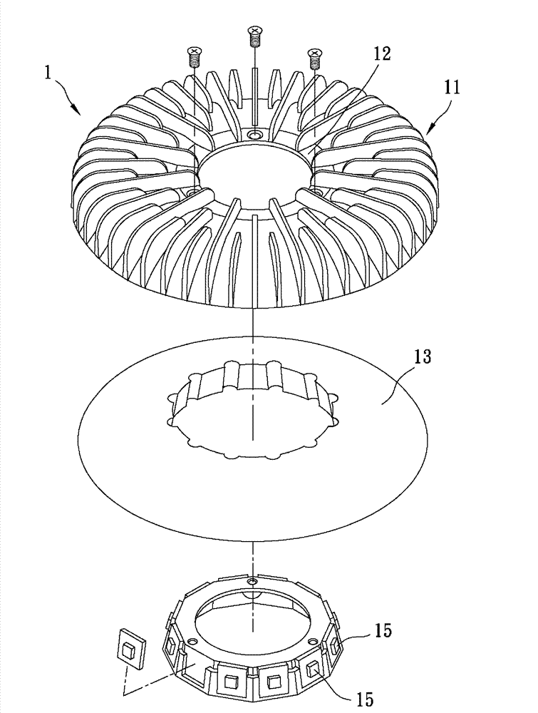
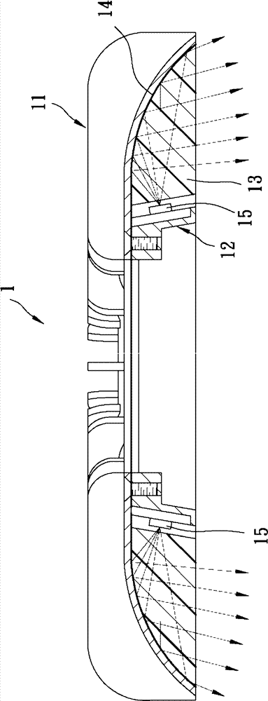
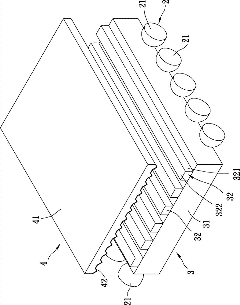
[0034] refer to image 3 , Figure 4 , Figure 5 , the first preferred embodiment of the light emitting device of the present invention is a down-illuminated lamp, which can be installed on the ceiling of a building to irradiate light downwards, but the implementation is not limited thereto. The light emitting device includes: a light source unit 2 , a light guide plate 3 and a reflective sheet 4 .

[0035] The light source unit 2 includes at least one light emitting diode 21. In this embodiment, a plurality of light emitting diodes 21 are arranged and divided into two groups and arranged on the left and right sides of the light guide plate 3, and the light emitting diodes 21 on the same side are arranged front and back. The present invention does...


PUM


Abstract

A light emitting device, a light-downward lamping tool, and a light guiding plate employed by the light-downward lamping tool. The light emitting device comprises a light source unit, the light guiding plate for transmitting the light of the light source unit and a reflective sheet; the reflective sheet reflects the light coming from the light guiding plate back to the light guiding plate, comprises a plurality of reflective micro-structures protruding towards the light guiding plate, and each reflective micro-structure is provided with a vertical angle a (90 <=a<=170 degrees). The reflective sheet is provided with the micro-structures with good reflective effect, and combined with the proper vertical angle design of the reflective micro-structure, the reflective lights can be uniformly guided to a needed light emitting angle. The light emitting device can be applied in the light-downward lamping tool or other light emitting equipment.

Description

technical field [0001] The present invention relates to a light-emitting device, a lamp and a light guide plate, in particular to a light-emitting device using a light-emitting diode (LED) as a light source, a down-illuminated lamp with the structure of the light-emitting device and a lamp used for the down-illuminated lamp light guide plate. Background technique [0002] refer to figure 1 , figure 2 , is a lighting device 1 disclosed in Taiwan Patent No. I329182, comprising: a roughly bowl-shaped lampshade 11, a socket 12 locked in the lampshade 11, and a socket set around the lampshade 11 The light guide plate 13 between the socket 12 , a reflective layer 14 attached to the inner surface of the lampshade 11 , and a plurality of LEDs 15 mounted on the socket 12 and facing the light guide plate 13 . The light emitted by the light-emitting diode 15 is guided by the light guide plate 13, mixed in the light guide plate 13, and then reflected downward by the reflective layer...

Claims


Application Information

Patent Timeline
IPC IPC(8): F21S8/00F21S8/04F21V13/04G02B6/00F21Y101/02F21Y115/10
Inventor 陈信宏郭俊良林正丰
Owner CHI MEI CORP
Why Eureka
Try Eureka