Double-speed winding switch reluctance motor

A switched reluctance motor, low-speed winding technology, applied in the shape/pattern/structure of winding conductor, magnetic circuit static parts, magnetic circuit shape/pattern/structure, etc., can solve difficult high-performance requirements, restrict promotion, etc. problems, to achieve high-performance output, wide speed range, small moment of inertia

Active Publication Date: 2013-06-19
SOUTHEAST UNIV
View PDF6 Cites 11 Cited by
  • Summary
  • Abstract
  • Description
  • Claims
  • Application Information

AI Technical Summary

Problems solved by technology

The switched reluctance motor with the above-mentioned traditional winding structure can only show good performance in a certain operating area in the low-speed area or high-speed area, and it is difficult to meet the high-performance requirements in the entire operating range at the same time, which limits its application in electric motors. Further promotion and development of applications such as automobiles that require both short-term low-speed high-torque output capability and wide range of high-speed speed regulation

Method used


Image

  • Double-speed winding switch reluctance motor
  • Double-speed winding switch reluctance motor
  • Double-speed winding switch reluctance motor

Examples


Embodiment 1

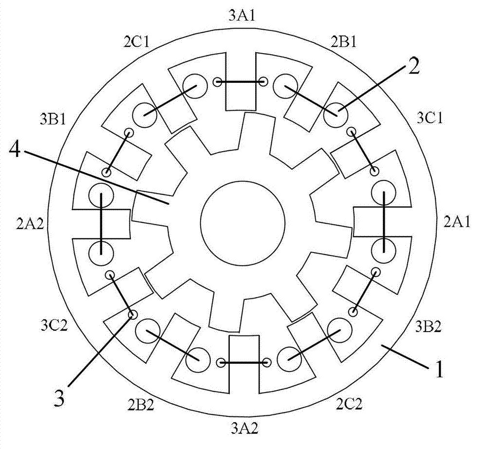
[0034] Embodiment 1: Take the structure of a three-phase stator, 12-slot rotor, and 8-pole switched reluctance motor as an example for illustration.

[0035] Such as figure 2 As shown, in the three-phase stator 12-slot rotor 8-pole switched reluctance motor of this embodiment, the stator 1 is provided with 12 stator teeth. Among the two adjacent stator teeth, one has a low-speed winding coil suitable for low-speed operation, and the other has a high-speed winding coil suitable for high-speed operation, that is, there are still 12 winding coils on the stator, which are called in turn in the counterclockwise direction: The first low-speed concentrated coil 2A1, the first high-speed concentrated coil 3C1, the second low-speed concentrated coil 2B1, the second high-speed concentrated coil 3A1, the third low-speed concentrated coil 2C1, the third high-speed concentrated coil 3B1, the fourth low-speed concentrated coil 2A2, the Four high-speed concentrated coils 3C2, fifth low-spe...

Embodiment 2

[0045] Embodiment 2: Take the structure of a four-phase stator, 8-slot rotor, and 6-pole switched reluctance motor as an example for illustration.

[0046] Such as Figure 5 As shown, in the four-phase stator 8-slot rotor 6-pole switched reluctance motor of this embodiment, the stator 1 is provided with 8 stator teeth. Among the two adjacent stator teeth, one has a low-speed winding coil suitable for low-speed operation, and the other has a high-speed winding coil suitable for high-speed operation. The number of turns of the low-speed winding coil and the high-speed winding coil are different from the wire diameter. There are still 8 winding coils, which are called in turn in the counterclockwise direction: the first low-speed concentrated coil 2A1, the second high-speed concentrated coil 3A1, the second low-speed concentrated coil 2B1, the third high-speed concentrated coil 3B1, the fourth low-speed concentrated coil 2A2, The fifth high-speed concentrated coil 3A2, the fifth...

Embodiment 3

[0053] Embodiment 3: The structure of the switched reluctance motor with a two-phase stator, four slots and a rotor with six poles is taken as an example for illustration.

[0054] Such as Figure 7 As shown, in the two-phase stator 4-slot rotor 6-pole switched reluctance motor of this embodiment, the stator 1 is provided with 4 stator teeth. Among the two adjacent stator teeth, one has a low-speed winding coil suitable for low-speed operation, and the other has a high-speed winding coil suitable for high-speed operation. The number of turns of the low-speed winding coil and the high-speed winding coil are different from the wire diameter. There are still 4 winding coils, which are called in turn in the counterclockwise direction: the first low-speed concentrated coil 2A1, the second high-speed concentrated coil 3A1, the fourth low-speed concentrated coil 2A2, and the fifth high-speed concentrated coil 3A2.

[0055] The low-speed concentrated winding 2 includes a first low-sp...


PUM


Abstract

The invention discloses a double-speed winding switch reluctance motor. Stator teeth in even number are arranged on a stator, and concentrated windings are arranged on the stator teeth. The concentrated windings comprise low-speed concentrated windings and high-speed concentrated windings, and the number of turns of the low-speed concentrated windings is more than that of the high-speed concentrated windings. The wire diameter of each low-speed concentrated winding is smaller than that of one high-speed concentrated winding, and in two adjacent stator teeth, one stator tooth is coiled with a low-speed concentrated winding, and the other stator tooth is coiled with a high-speed concentrated winding. A low-speed concentrated winding is arranged on the opposite side of another low-speed concentrated winding in the radial direction of the stator, and moreover the two low-speed concentrated windings are connected in series or in parallel to form a one-phase low-speed winding. The opposite side of each high-speed concentrated winding is provided with another high-speed concentrated winding in the radial direction of the stator, and the two high-speed concentrated windings are connected in series or in parallel to form a one-phase high-speed winding. The double-speed winding switch reluctance motor can output large torque in low-speed operation, and has a wide speed regulation range in high-speed operation.

Description

technical field [0001] The invention belongs to the technical field of motor manufacturing, and in particular relates to a two-speed winding switched reluctance motor. Background technique [0002] With the development of power electronic device technology, microelectronic technology and automatic control technology, especially the price increase caused by the export restrictions of rare earth permanent magnet materials, the application of switched reluctance motors will become more and more extensive. The switched reluctance motor has a double salient pole structure. The stator and rotor are made of ordinary silicon steel sheets laminated. There is neither permanent magnet nor winding on the rotor. There are only concentrated winding coils on the stator. It works according to the principle of "minimum reluctance". Switched reluctance motors have the advantages of simple manufacturing process, low cost, firm structure, good fault tolerance, and suitable for high-speed operat...

Claims


Application Information

Patent Timeline
Patent Type & Authority Applications(China)
IPC IPC(8): H02K1/14H02K3/20H02K3/28
Inventor 花为华浩吴中泽程明
Owner SOUTHEAST UNIV
Why Eureka
Try Eureka