Angle face clamping device and clamping method thereof

A technology of clamping device and angle surface, which is applied in the field of fixtures and fixtures, can solve the problems of scrapped parts, rising processing costs, and many pressing mechanisms

Active Publication Date: 2014-06-04
SHENYANG AIRCRAFT CORP
View PDF5 Cites 3 Cited by
  • Summary
  • Abstract
  • Description
  • Claims
  • Application Information

AI Technical Summary

Problems solved by technology

The current fixture usually adopts one-way screw-in clamping and pressing for parts with angled surfaces, such as figure 1 As shown, it needs to be respectively fixed on the horizontal plane and the vertical plane. This kind of fixture clamping and pressing method requires many pressing mechanisms, the cycle of fixture processing will increase, and the processing cost will increase accordingly. The state changes after processing, so that the lateral compaction often appears in a point-contact compaction state, which is easy to crush the parts, resulting in quality defects of the parts, or even scrapping the parts; at the same time, there are many steps in the clamping steps, which directly affects the processing efficiency. , especially for machining longer parts

Method used


Image

  • Angle face clamping device and clamping method thereof
  • Angle face clamping device and clamping method thereof

Examples


Embodiment Construction

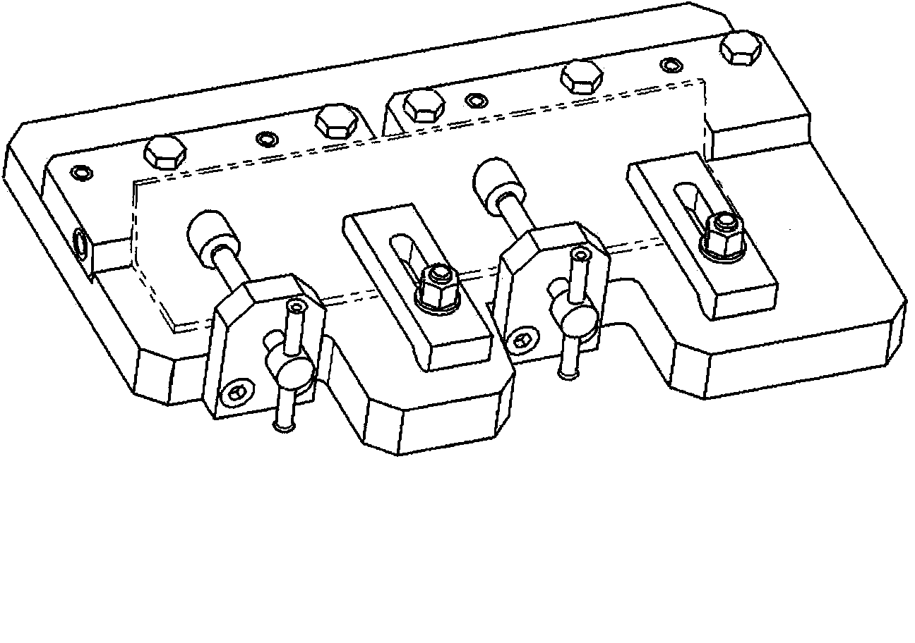
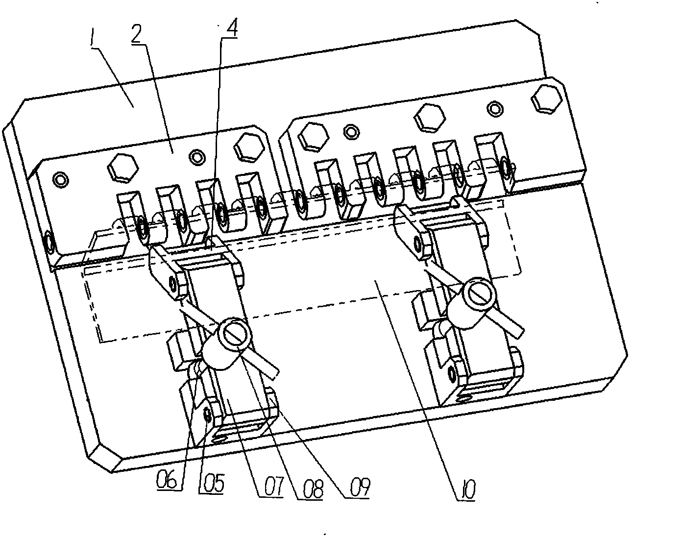
[0014] Such as figure 2 As shown, an angle surface clamping device is provided with a positioning assembly 2 at one end of the bottom plate 1, and a fork seat 9 at the other end. The end of the fork seat 9 is movably connected to the pressure plate 7 through a cylindrical pin 5, and the pressure plate 7 is The end is provided with a briquetting block 4, and the front end of the briquetting block 4 is a semi-cylindrical structure, and is bent downward at an angle along the surface of the pressing plate 7; the fork seat 9 and the pressing plate 7 are respectively provided with corresponding opening slots and opening slots. A bolt 6 is arranged inside, and the handle nut 8 is threadedly connected with the upper part of the bolt 6 and presses the pressure plate 7 tightly.

[0015] The positioning assembly 2 is divided into several pieces and evenly distributed, and several opening grooves are provided on the surface of the positioning assembly 2, and coaxial through holes are pro...


PUM


Abstract

The invention relates to an angle face clamping device. A positioning assembly is arranged at one end of a base plate and the other end of the base plate is provided with a fork seat. One end of the fork seat is connected with a pressing plate in a moving mode through a straight pin. One end of the pressing plate is provided with a pressing block. The front end of the pressing block is of a semi-cylindrical structure and bends downwards to form an angle along the surface of the pressing plate. Opened grooves which are opposite to each other in position are formed in the fork seat and the pressing plate respectively. Bolts are arranged in the opened grooves and handle nuts are in threaded connection with the upper portions of the bolts and press the pressing plate. The angle face clamping device can rapidly position parts and is simple in clamping method and capable of improving processing efficiency and ensuring the quality of processed parts.

Description

technical field [0001] The invention relates to an angle surface clamping device and a clamping method thereof, belonging to a tooling fixture. Background technique [0002] The clamping and clamping of angled parts during machining is the basic guarantee for the stable processing state of parts and qualified parts. The current fixture usually adopts one-way screw-in clamping and pressing for parts with angled surfaces, such as figure 1 As shown, it needs to be respectively fixed on the horizontal plane and the vertical plane. This kind of fixture clamping and pressing method requires many pressing mechanisms, the cycle of fixture processing will increase, and the processing cost will increase accordingly. The state changes after processing, so that the lateral compaction often appears in a point-contact compaction state, which is easy to crush the parts, resulting in quality defects of the parts, or even scrapping the parts; at the same time, there are many steps in the cl...

Claims


Application Information

Patent Timeline
Patent Type & Authority Applications(China)
IPC IPC(8): B23Q3/06
CPCB23Q3/062
Inventor 李兴云张伟强
Owner SHENYANG AIRCRAFT CORP
Why Eureka
Try Eureka