Sealing device

A technology for sealing devices and holes, which is applied to the sealing of engines, engine components, machines/engines, etc., which can solve the problems of damaged sealing functions, the detachment of the sealing device 200, and the reduction of the force of fitting and fixing, so as to achieve simple structure, The effect of suppressing the separation of the sealing device

Active Publication Date: 2014-09-10
EAGLE INDS
View PDF12 Cites 4 Cited by
  • Summary
  • Abstract
  • Description
  • Claims
  • Application Information

AI Technical Summary

Problems solved by technology

On the other hand, when a resin material such as PPS is used as the material of the shaft housing 30 for the purpose of weight reduction, etc., due to the influence of fatigue and thermal expansion during high-temperature use, the contact with the cylindrical portion 211 of the housing 210 will be caused. The small-diameter hole portion 31 fits and fixes with reduced force
Therefore, when a force acting in the direction opposite to the X direction in the figure acts on the sealing device 200, the sealing device 200 will come out, resulting in damage to the sealing function.

Method used


Image

  • Sealing device
  • Sealing device
  • Sealing device

Examples


Embodiment 1

[0061] combine Figure 1 ~ Figure 4 The sealing device of Embodiment 1 of the present invention will be described.

[0062]

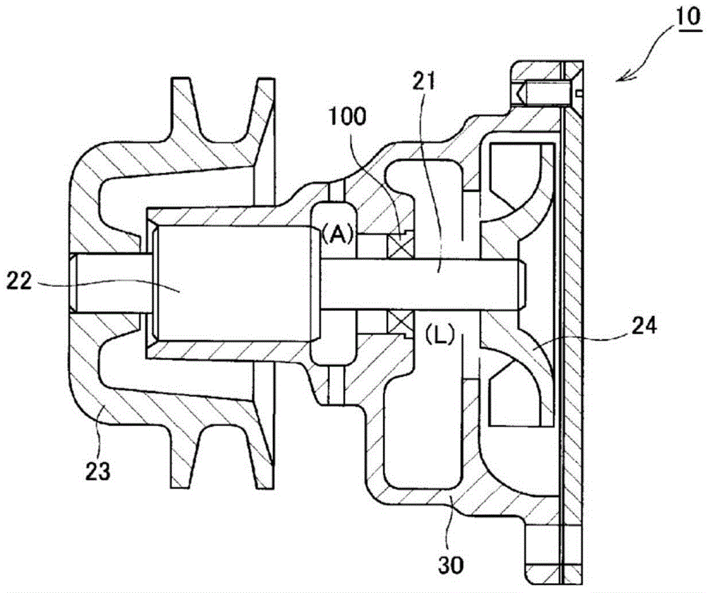
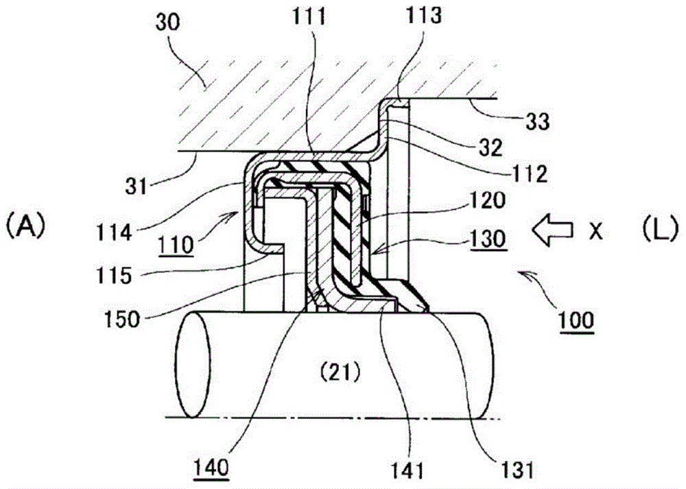
[0063] combine figure 1 An application example of the sealing device 100 according to the embodiment of the present invention will be described. figure 1 It is a schematic sectional view of the water pump 10 for an automobile. The water pump 10 includes a shaft 21 and a shaft housing 30 having a shaft hole through which the shaft 21 passes. A bearing 22 for smooth rotation of the rotating shaft 21 is installed on the rotating shaft 21 . A pulley 23 is attached to one end of the rotating shaft 21 to provide rotational driving force by rotating a belt (not shown), and an impeller 24 for pressure-feeding cooling water (LLC) is attached to the other end. The sealing device 100 of this embodiment is disposed in the annular gap between the shaft 21 and the shaft housing 30 to suppress leakage of cooling water to the outside (ie, the side (A) opposite ...

Embodiment 2

[0076] Figure 5 Example 2 of the present invention is shown. In this embodiment, a modified example of the case of the above-described first embodiment will be described. In the above-mentioned Embodiment 1, the claw protruding from the end of the flange portion of the housing has a ring shape. In the above-mentioned case where the claws are ring-shaped, the rigidity of the claws is high, so the wall thickness of the parts constituting the housing and the diameter of the claws will cause excessive force required to deform toward the inner peripheral surface, making installation Insertion force is too high when sealing the device. Thus, in the present embodiment, the claw portion is partially provided in the circumferential direction. The structures and functions other than the casing are the same as those in Embodiment 1, so the same symbols are added to the parts with the same structure, and their descriptions are omitted.

[0077] The metal casing (bush) 160 of this emb...

Embodiment 3

[0084] Figure 6 Example 3 of the present invention is shown. Depending on the relationship between the diameter of the rotating shaft and the diameter of the shaft hole of the shaft housing, there are situations where the annular gap to be sealed by the sealing device is very large. Therefore, in the sealing device of this embodiment, by providing the housing with an S-shaped section, it has elasticity in the radial direction, and even if it is used in a large annular gap, it will not deteriorate the mountability, and the sealing can be fully exerted. sex. The structure other than the housing is basically the same as that shown in the first embodiment above, so it will be briefly described.

[0085] In the sealing device 100 of the present embodiment, as in the first embodiment described above, a metal housing (bushing) 170, a metal ring 120a, a first sealing member 130a, a second sealing member 140a, and a backup ring 150a are provided. In the case of this embodiment, the...


PUM


Abstract

Provided is a sealing device configured so that, even if a housing consists of a resin, the coming out of the sealing device from the housing is prevented by a simple configuration. A case (110) is characterized by comprising: a cylindrical section (111) which is fitted and engaged with the internal peripheral surface of a small-diameter hole (31); a flange (112) which extends from an end of the cylindrical section (111) toward the outer peripheral surface side and which positions a sealing device (100) by abutting against the stepped surface (32) between the small-diameter hole (31) and a large-diameter hole (33); and a claw (113) which is configured so as to tilt toward the outer peripheral surface side as the claw (113) extends along the axis from an end of the flange (112) in the direction opposite the cylindrical section (111).

Description

technical field [0001] The invention relates to a sealing device for sealing an annular gap between a shaft and a shaft housing. Background technique [0002] combine Figure 8 A prior art sealing device will be described. Figure 8 It is a schematic cross-sectional view showing the situation when the conventional sealing device is installed. [0003] The sealing device 200 is used to seal the annular gap between the shaft housing 30 having the shaft hole and the rotating shaft 21 passing through the shaft hole. The shaft hole provided in the shaft housing 30 includes a small-diameter hole portion 31 and a large-diameter hole portion 33 . The sealing device 200 has a metal case 210 in which a sealing member and the like are assembled to form a bush. [0004] The sealing device 200 described above is attached from the side of the large-diameter hole 33 to the side of the small-diameter hole 31 in the direction of the arrow X in the figure. The housing 210 of the sealing de...

Claims


Application Information

Patent Timeline
Patent Type & Authority Applications(China)
IPC IPC(8): F16J15/16F16J15/32
CPCF01D25/183F16J15/3228F16J15/3224F16J15/3252
Inventor 老山幸一郎
Owner EAGLE INDS
Why Eureka
Try Eureka