Double-suction impeller

A double-suction impeller and blade technology, applied in the field of machinery, can solve the problems of large impact loss at the impeller outlet, low cavitation resistance and efficiency of the impeller, and narrow application range of double-suction pumps, so as to eliminate secondary backflow and broaden the application range , The effect of expanding the specific speed range

Inactive Publication Date: 2015-01-14
兰州国器装备制造集团有限公司
View PDF5 Cites 6 Cited by
  • Summary
  • Abstract
  • Description
  • Claims
  • Application Information

AI Technical Summary

Problems solved by technology

[0005] The purpose of the present invention is to provide a double-suction impeller, which solves the problems in the prior art that the impact loss at the outlet of the impeller is large, the anti-cavitation ability and efficiency of the impeller are low, and the application range of the double-suction pump is narrow.

Method used


Image

  • Double-suction impeller
  • Double-suction impeller
  • Double-suction impeller

Examples


Embodiment Construction

[0024] The present invention will be described in detail below in conjunction with the accompanying drawings and specific embodiments.

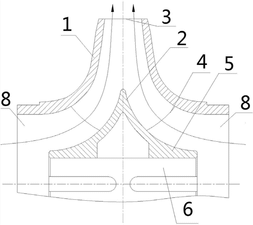
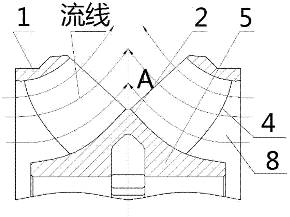
[0025] The invention provides a double-suction impeller, which includes a front cover 1, a rear cover 2, blades 4, a hub 5 and a shaft hole 6, the outlet side of the water outlet 3 is V-shaped, and the apex of the V is at the rear cover. 2 is provided with an upwardly protruding baffle 7, the two sides of the baffle 7 are inwardly concave arc, and the shape of the baffle 7 transitions smoothly as the flow channel changes. The invention increases the specific rotational speed of the impeller, minimizes hydraulic loss, has a symmetrical structure, has no axial force, and runs smoothly.

[0026] The working principle of the double-suction impeller of the present invention is: the integrated body of the hub 5, the rear cover 2 and the partition 7 and the front cover 1 form a double flow channel 8, the liquid flow enters the flow channel 8, and th...


PUM


Abstract

The invention discloses a double-suction impeller, comprising a front cover board, a rear cover board, blades, a hub and a shaft, wherein the outlet edge of a water outlet is V-shaped; a partition plate which protrudes upwards is arranged on the peak of the V-shape and on the rear cover board; two edges of the partition plate are respectively in an inward concave arc shape; the partition plate is in smooth transition along the runner change shape. According to the double-suction impeller, the specific speed of the impeller is increased, the hydraulic loss is reduced to the maximal extent, and the double-suction impeller is symmetric in structure, free of axial force and stable in operation.

Description

technical field [0001] The invention belongs to the technical field of machinery (pumps), and in particular relates to a double-suction impeller. Background technique [0002] At present, pumps are divided into centrifugal pumps, mixed-flow pumps and axial-flow pumps according to the range of specific speed, that is, when the specific speed (ie specific speed) is 30-300, it belongs to centrifugal pumps, when it is 300-500, it belongs to mixed-flow pumps, and when it is 500-1000, it belongs to centrifugal pumps. It is an axial flow pump. Specific speed and combine Figure 5 It can be seen that when the flow rate and speed of the pump are constant, and the size of the suction port is roughly equal, the smaller the specific speed is, the higher the head is, and the larger the specific speed is, the lower the head is. with n s Numerical increase, D 2 / D 0 value gradually decreases. The outlet side of the mixed-flow pump becomes inclined, because as n s Raise, D 2 / D 0 ...

Claims


Application Information

Patent Timeline
Patent Type & Authority Applications(China)
IPC IPC(8): F04D29/22F04D29/66
CPCF04D29/2211F04D29/667
Inventor 张涛吴应德马柏青杨德旭马文生王成祁应军
Owner 兰州国器装备制造集团有限公司
Why Eureka
Try Eureka