

in situ artificial bladder prosthesis
A prosthetic and artificial technology, applied in the field of in situ artificial bladder prosthesis, can solve the problems of antibiotic treatment effectiveness barriers and other issues
- Summary
- Abstract
- Description
- Claims
- Application Information
AI Technical Summary
Problems solved by technology
Method used
Image

Examples
Embodiment Construction
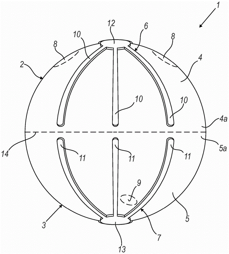
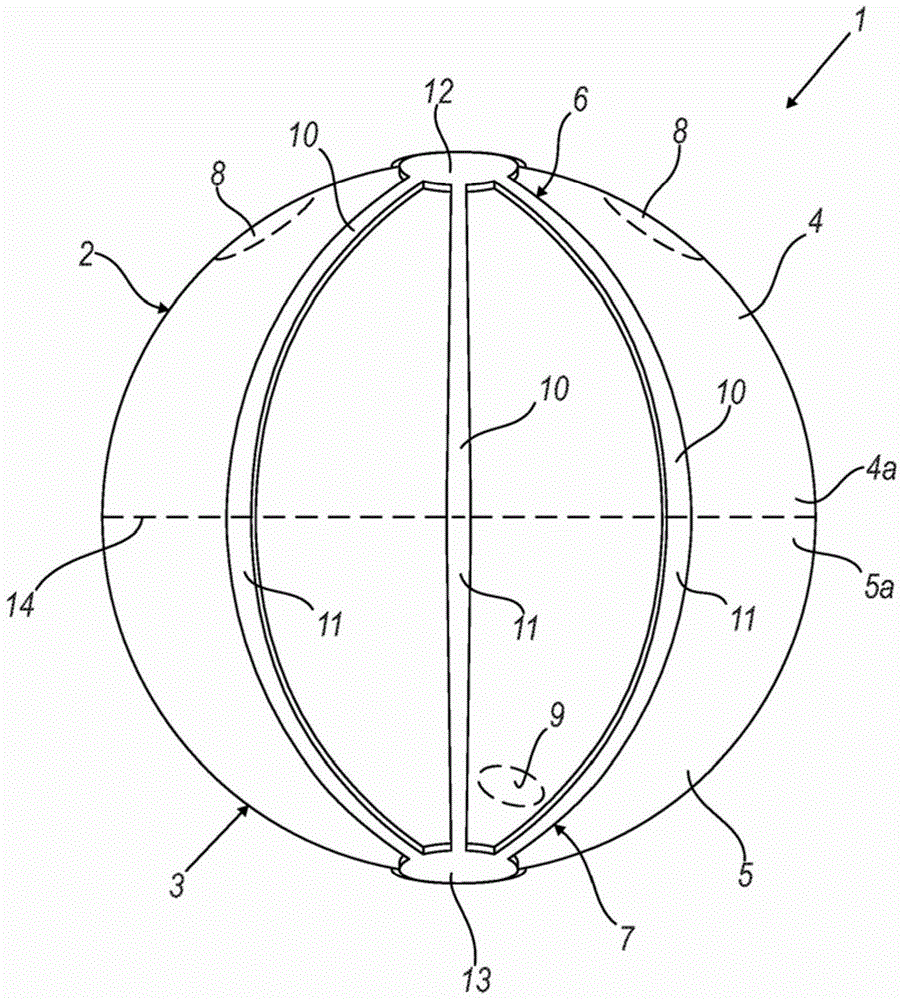
[0026] Referring to the accompanying drawings, reference numeral 1 designates an in situ artificial bladder endoprosthesis according to the present invention. The endoprosthesis 1 comprises two parts 2, 3 joined together. Preferably, parts 2, 3 are identical to each other. Preferably, the parts 2, 3 are connected to each other by resorbable sutures.
[0027] The parts 2, 3 are substantially hemispherical in form and are coupled in such a way that the concave surfaces of the parts 2, 3 face each other. In this way, the two joined parts 2, 3 define a tight enclosure for containing urine. The enclosure has a roughly between 100cm 3 with 900cm 3 Between, preferably 400cm 3 volume of.
[0028] The first part 2 is intended to be connected to the patient's ureter. The second part 3 is intended to be connected to the patient's urethra.
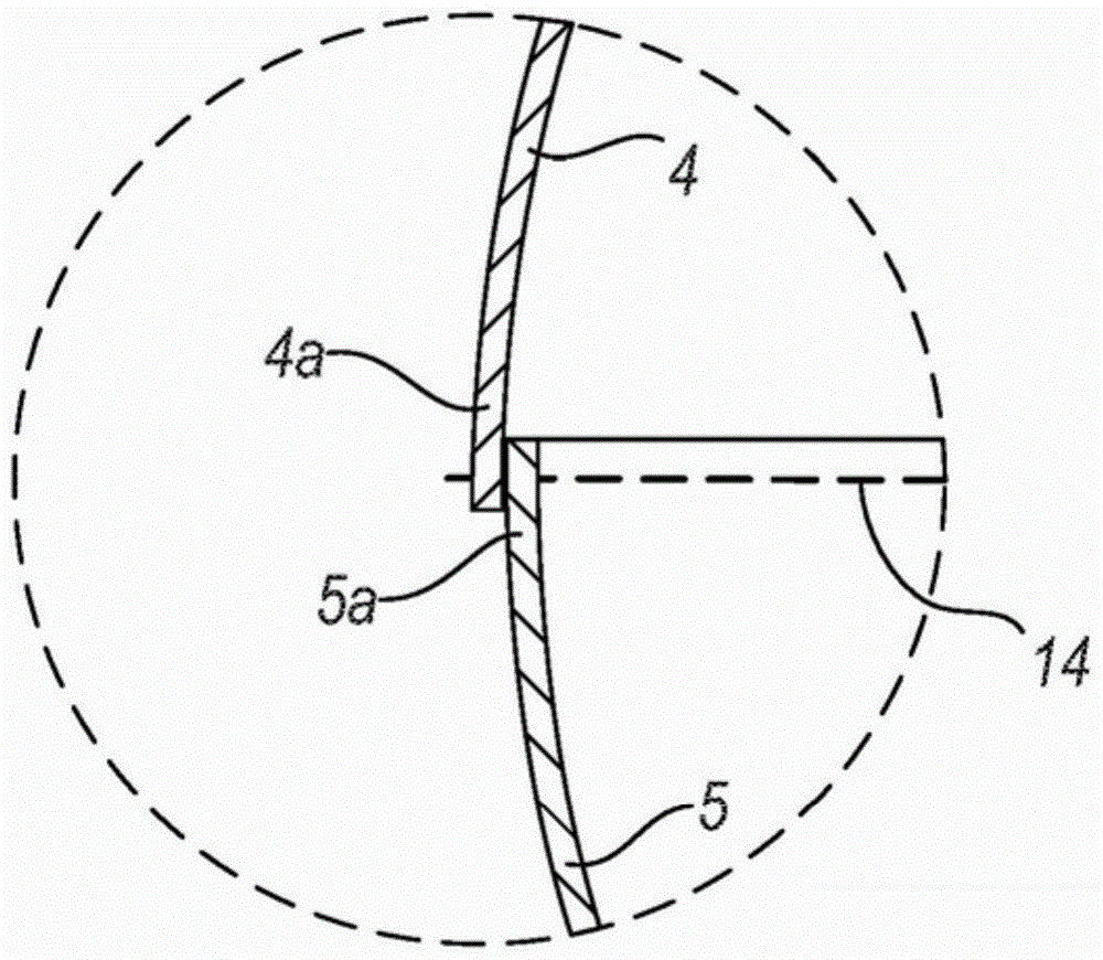
[0029] Each part 2,3 comprises a resorbable cap piece 4,5. The cap parts 4, 5 are connected to each other.
[0030] In particular, the cap ...
PUM
 Abstract
Description
Claims
Application Information