Underwater friction stitch welding local dry method small draining device

A technology of local dry method and drainage device, applied in welding equipment, non-electric welding equipment, metal processing equipment, etc., can solve problems such as poor welding quality

Inactive Publication Date: 2015-11-04
TIANJIN UNIV
View PDF12 Cites 1 Cited by
  • Summary
  • Abstract
  • Description
  • Claims
  • Application Information

AI Technical Summary

Problems solved by technology

[0004] The purpose of the present invention is to overcome the deficiencies of the prior art and provide a small-scale underwater friction stitch welding partial dry method drainage device. In order to solve the problem of poor welding quality of friction stitch w

Method used


Image

  • Underwater friction stitch welding local dry method small draining device
  • Underwater friction stitch welding local dry method small draining device

Examples


Embodiment Construction

[0013] The technical solutions of the present invention will be further described below in conjunction with specific embodiments.

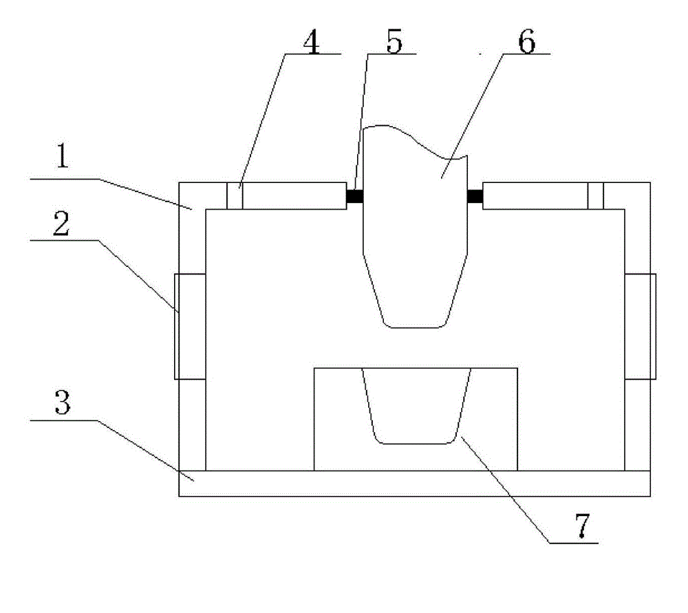
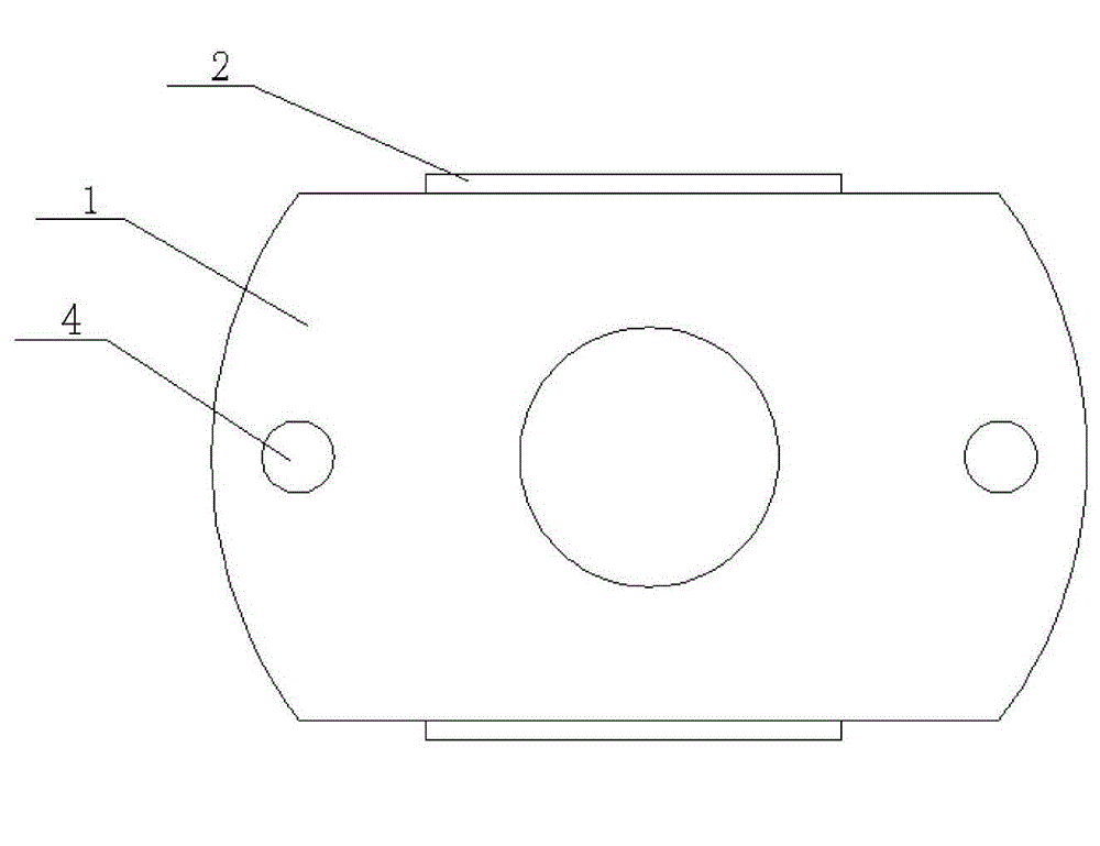
[0014] as attached figure 1 and 2 As shown, the structure of the drainage device of the present invention, wherein 1 is a drainage cover, 2 is an observation window, 3 is a drainage sponge layer, 4 is an air inlet hole, 5 is a sealing material layer, 6 is a stopper rod, and 7 is a workpiece to be welded .

[0015] The entire drainage cover is a cylindrical shell with an opening at the lower end, and a plane is milled symmetrically in the vertical direction to facilitate the installation of the observation window; a through hole is set at the center of the upper end surface of the drainage cover, and a sealing material layer is set in the through hole; The air intake holes are arranged symmetrically on the left and right sides of the through hole to facilitate the connection of the air pipe for ventilation, so as to ensure the air environment in ...


PUM


Abstract

The invention discloses an underwater friction stitch welding local dry method small draining device. A whole draining cover is a cylindrical shell, an opening is formed at the lower end of the whole draining cover, and planes are symmetrically milled in the vertical direction. A through hole is formed in the central position of the upper end face of the draining cover, and a sealed material layer is arranged in the through hole; air inlets are symmetrically formed on the left side and the right side of the through hole; observation windows are formed on the planes milled in the vertical direction of the draining cover; and a draining sponge layer is arranged on the lower end face of the draining cover, and connection between waterproof glue and the draining cover is utilized, so that connection airtightness is ensured. The sealing material layer is a solid annular sealing material layer and is in tight contact with a stopper rod; in the high-speed rotating process of the stopper rod, the airtightness can be ensured, and wear resistance is achieved; the problems that the underwater friction stitch welding quality is poor, and air environment needs to be built underwater for welding are solved. The aims of obtaining the better welding joint quality, optimizing the underwater welding working procedure, and expanding the technical parameter range are achieved.

Description

technical field [0001] The invention belongs to the technical field of solid-phase welding, and more specifically relates to a novel friction stitch welding local dry drainage device. Background technique [0002] Friction stitch welding is a new type of solid phase joining method. Friction stitch welding was invented in 1992 by WM Thomas, EDNicholas et al. of TWI. In the past ten years, Europe has invested a lot of energy in related basic research. Domestically, Beijing Institute of Petrochemical Technology and Tianjin University have done preliminary research on friction stitch welding. The unit hole welding of friction stitch welding is called Friction Hydro Pillar Processing (FHPP). Its principle is to use the consumable characteristic rod (which can be called the stopper rod) to drive the stopper rod through the driving device Rotate, the stopper rod descends while rotating, and the stopper rod contacts and rubs against the plug hole (the hole to be welded) to form p...

Claims


Application Information

Patent Timeline
IPC IPC(8): B23K20/26B23K20/12
Inventor 贺钧王志江崔雷邓彩艳王东坡
Owner TIANJIN UNIV
Why Eureka
Try Eureka