Suction cup manipulator

A manipulator and suction cup technology, applied in the field of suction cup manipulators, can solve the problems of insufficient positioning accuracy, large impact, high price, etc., and achieve the effect of avoiding damage and reducing costs.

Inactive Publication Date: 2018-04-10
TSINGHUA UNIV +1
View PDF8 Cites 1 Cited by
  • Summary
  • Abstract
  • Description
  • Claims
  • Application Information

AI Technical Summary

Problems solved by technology

[0002] The suction cup manipulator is one of the commonly used manipulators in mechanical processing and semiconductor wafer processing. The suction cup manipulator in the prior art often causes damage to the workpiece due to insufficient positioning accuracy, especially when processing fragile materials. Due to insufficient positioning accuracy, when the suction cup is in contact with the workpiece, the driving mechanism is still driving the suction cup to move, resulting in excessive pressure or impact on the workpiece, resulting in damage to the workpiece
In the prior art, in order to avoid damage to the workpiece, a higher-precision sensor is often used to position the manipulator, but a higher-precision sensor means a higher price, resulting in an increase in equipment cost

Method used


Image

  • Suction cup manipulator
  • Suction cup manipulator
  • Suction cup manipulator

Examples


Embodiment 1

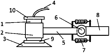
[0015] Such as figure 1 As shown, the suction cup type manipulator of the present embodiment includes a pick-up device and a pick-up arm 13; Shaft 1, wherein, the lower surface of the vacuum chuck 3 is provided with a flexible pad, the upper end of the sliding shaft 1 is provided with an upper limit block 10, and the lower end of the sliding shaft 1 is provided with a lower limit block 9; the pick-up arm 13 is provided with a sleeve 2 at one end, the sliding shaft 1 is set in the sleeve 2, the distance between the upper limit block 10 and the lower limit block 9 is greater than the length of the sleeve 2, the The sleeve 2 is arranged between the upper limit block and the lower limit block 9; when the sliding shaft 1 is opposite to the force direction of the sleeve 2, the sliding shaft 1 is inside the sleeve 2 slide.

[0016] When the suction cup-type manipulator of this embodiment picks up the workpiece, the suction cup descends. After touching the workpiece, the pick-up arm...

Embodiment 2

[0018] On the basis of Embodiment 1, the pick-up arm 13 includes a mechanical section 8 and a sleeve section 5; the mechanical section 8 and the sleeve section 5 are hinged, and the hinge shaft 6 is horizontally arranged, and the upper side of the hinge shaft 6 and A spring 7 is arranged on the lower side, and the two ends of the spring 7 are respectively connected with the mechanical section 8 and the sleeve section 5 . The sleeve section 5 is connected with the mechanical section 8 through the rotating shaft and the spring 7, so that the sleeve section 5 and the mechanical section 8 can produce a certain angle. Since the angle of the pick-up device and the sleeve section 5 changes synchronously, this arrangement can Change the angle of the pick-up device to adapt to the actual position of the workpiece and the plane of the workpiece table. Because the spring 7 is used to tighten the two ends, the angle of the suction cup can be automatically changed when the pick-up device i...

Embodiment 3

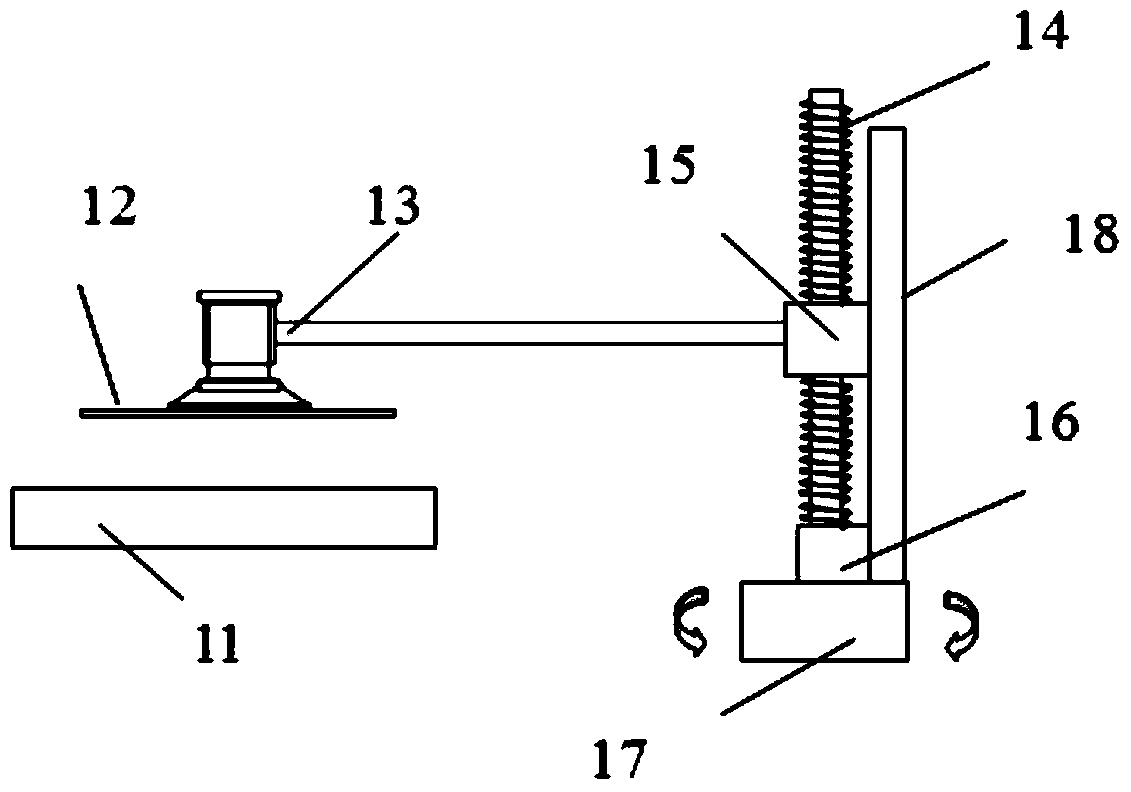
[0020] Such as Figure 2-3 As shown, in addition to the structure of the above-mentioned embodiments, the suction cup robot arm of this embodiment also includes a slider 15 connected to the other end of the picking arm 13, a slide rail 18 forming a sliding pair with the slider 15, A lead screw 14 that cooperates with the slider 15 to form a ball screw pair, a driving device 16 that drives the lead screw 14 to rotate, and a rotary table 17 connected to the bottom end of the lead screw 14 and the slide rail 18, wherein , the lead screw 14 and the slide rail 18 are all arranged vertically. The lower limit block is provided with a displacement sensor that senses the distance of the sleeve.

[0021] The specific implementation steps of this embodiment will be described with respect to the workflow of the sucker-type manipulator in this embodiment in the laser annealing process for semiconductor wafer 12 processing:

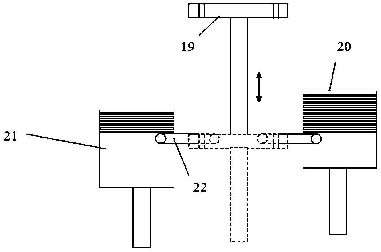
[0022] The entry / exit table 19 is located at the entry / exit pos...


PUM


Abstract

The invention discloses a sucker type manipulator. The problems that sucker type manipulators in the prior art are inaccurate in positioning and prone to damage workpieces are mainly solved. According to the technical scheme, the sucker type manipulator comprises a pick-up device and a pick-up arm. The pick-up device comprises a vacuum chuck, a vacuum pipe which is communicated with the vacuum chuck and a sliding shaft of which the lower end is connected with the upper surface of the vacuum chuck. A soft liner is disposed on the lower surface of the vacuum chuck; an upper limiting block is disposed at the upper end of the sliding shaft; a lower limiting block is disposed at the lower end of the sliding shaft; a sleeve is arranged at one end of the pick-up arm; the sliding shaft is arranged in the sleeve; the distance between the upper limiting block and the lower limiting block is larger than the length of the sleeve; the sleeve is disposed between the upper limiting block and the lower limiting block; when the forced directions of the sliding shaft and the sleeve are opposite, the sliding shaft slides in the sleeve. By means of the sucker type manipulator, the equipment cost can be reduced, and the damages to the workpieces are avoided.

Description

technical field [0001] The invention relates to a sucker-type manipulator, in particular to a sucker-type manipulator for picking and placing fragile workpieces. Background technique [0002] The suction cup manipulator is one of the commonly used manipulators in mechanical processing and semiconductor wafer processing. The suction cup manipulator in the prior art often causes damage to the workpiece due to insufficient positioning accuracy, especially when processing fragile materials. Due to insufficient positioning accuracy, when the suction cup has been in contact with the workpiece, the driving mechanism is still driving the suction cup to move, resulting in excessive pressure or impact on the workpiece, thereby causing damage to the workpiece. In the prior art, in order to avoid damage to the workpiece, a higher-precision sensor is often used to position the manipulator. However, a higher-precision sensor means a higher price, resulting in an increase in equipment cost...

Claims


Application Information

Patent Timeline
Patent Type & Authority Patents(China)
IPC IPC(8): B25J15/06
CPCB25J15/0625
Inventor 严利人张伟刘志弘周伟王全
Owner TSINGHUA UNIV
Why Eureka
Try Eureka