Compressor

A compressor and rotor core technology, applied in the field of compressors, can solve the problems of reducing compressor power consumption, etc., and achieve the effects of preventing discharge, reducing oil discharge rate, and good oil blocking effect

Active Publication Date: 2016-07-20
GREE ELECTRIC APPLIANCES INC OF ZHUHAI +1
View PDF8 Cites 6 Cited by
  • Summary
  • Abstract
  • Description
  • Claims
  • Application Information

AI Technical Summary

Problems solved by technology

[0007] The main purpose of the present invention is to provide a compressor to solve the problem that the method of r

Method used


Image

  • Compressor
  • Compressor
  • Compressor

Examples


Example Embodiment

[0030] It should be noted that the embodiments in the application and the features in the embodiments can be combined with each other if there is no conflict. Hereinafter, the present invention will be described in detail with reference to the drawings and in conjunction with the embodiments.

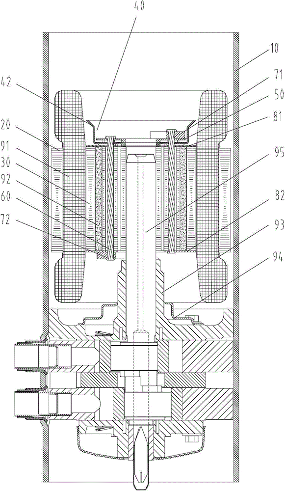
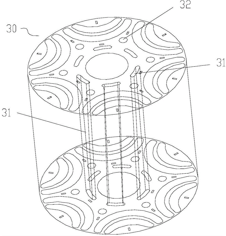
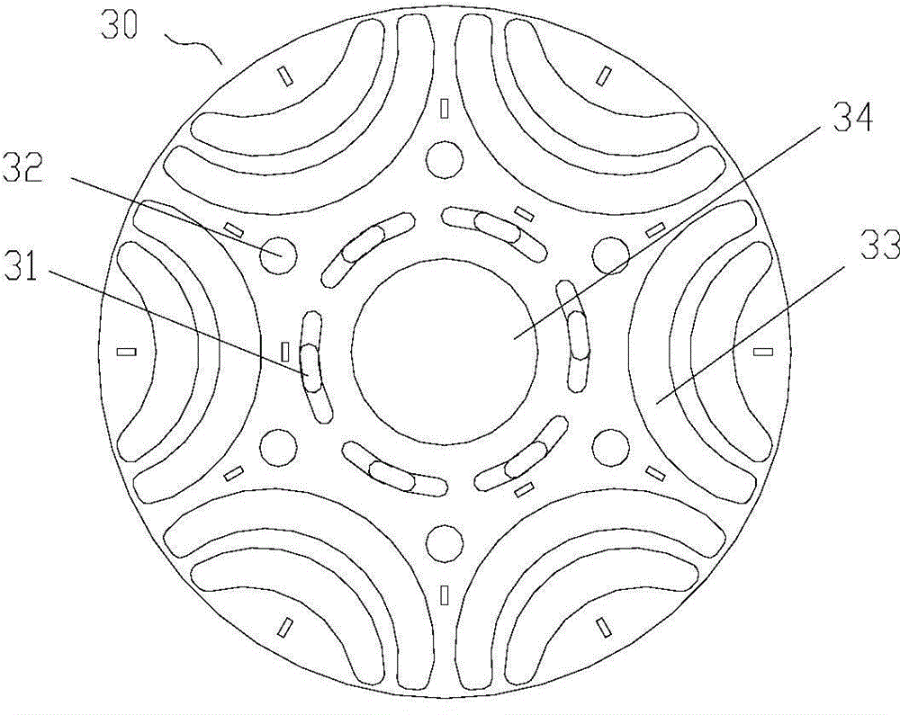
[0031] The present invention provides a compressor, please refer to Figure 1 to Figure 5 The compressor includes a housing 10 and a stator iron core 20 and a rotor iron core 30 arranged in the housing 10. The stator iron core 20 is arranged around the rotor iron core 30, and the rotor iron core 30 is arranged along its axial direction. The compressor further includes: a first baffle 40, the first baffle 40 includes a bottom plate 41 and an oil blocking side edge 42 provided on the upper side of the bottom plate 41, the first baffle 40 and the rotor core 30 The upper end faces of the two are arranged opposite to each other, so that the refrigerant flowing out of the circulation hole 31 pa...


PUM


Abstract

The invention provides a compressor comprising a shell, a stator core, a rotor core and a first baffle, wherein the stator core and the rotor core are arranged in the shell; the stator core is arranged around the rotor core; circulating holes formed along the axial direction of the rotor core are formed in the rotor core; and the first baffle comprises a bottom plate part and an oil retaining side edge arranged at the upper side of the bottom plate part, and the first baffle is opposite to the upper end surface of the rotor core, so that lubricating oil carried by a refrigerant comes into collision with the oil retaining side edge to form oil drops falling back below the rotor core after the refrigerant flowing out of the circulating holes passes through the bottom plate part. By using the compressor, the refrigerant can return from the upside to the downside of a motor of the compressor, so that the stroke of the refrigerant is increased; in addition, due to the adoption of the design of the non-swirl baffle located above the rotor core, an extremely good oil retaining effect is taken while no wind resistance is generated, and the condition that the lubricating oil is discharged from the compressor is avoided, so that the oil throughput rate of the compressor is effectively reduced, the performance of a unit is improved, and the power consumption of the compressor is reduced.

Description

technical field [0001] The invention relates to the field of fluid compression, in particular to a compressor. Background technique [0002] In the rolling rotor compressor, in order to reduce the oil discharge rate to improve the performance of the compressor and air conditioner, it is mainly realized by designing the structure of the stator and rotor of the motor, the height of the shell and the structure of the oil baffle above the rotor. [0003] The first two change the flow area and flow direction of the refrigerant from the bottom to the top of the motor, thereby changing the flow rate of the refrigerant, so that the refrigerant is slowly adsorbed on the surface of the structure. [0004] However, in the prior art, the flow path of the refrigerant is unreasonably designed, and there is only a single path between the motor and the casing, ignoring the flow path of the refrigerant inside the rotor. When the concentration of lubricating oil in the refrigerant is high, t...

Claims


Application Information

Patent Timeline
IPC IPC(8): F04C29/00
Inventor 邓敏黄伟才
Owner GREE ELECTRIC APPLIANCES INC OF ZHUHAI
Why Eureka
Try Eureka