Panel connection method

A technology of plate connection and plate, which is applied in the direction of thin plate connection, connecting components, mechanical equipment, etc., can solve the problems of easy falling off and damage, uneven plate surface, easy damage, etc., and achieve the effect of thickness guarantee

Inactive Publication Date: 2016-07-27
TONGXIANG BOFAN DECORATIVE MATERIAL CO LTD
View PDF14 Cites 4 Cited by
  • Summary
  • Abstract
  • Description
  • Claims
  • Application Information

AI Technical Summary

Problems solved by technology

[0014] Since the nailing position is set on the lower edge end, in order to ensure the strength, the lower edge end needs to have a certain thickness, so the thickness of the upper edge end needs to be sacrificed, and due to the limitation of the structure itself, the upper edge end, the upper edge butt end, and the lower edge end , The lower edge butt joint can not be made thicker, generally only 10%-20% of the overall height ratio, it is easy to be damaged during installation and transportation, especially the lower edge is easy to break during production and produce waste products; and in the During the installation, it needs to be nailed and fixed on a specific building surface such as the wall, which greatly increases the scrap rate. Therefore, the manufacturer only needs to add an additional set of equipment and use high-frequency mutual aid technology to strengthen the lower edge, and the installer generally can only purchase it. Increase the spare amount in advance to prevent excessive waste from delaying the construction period or shoddy and shoddy use during installation
[0015] In field application, walls, floors and other building surfaces will have varying degrees of height and inclination, which will cause problems such as uneven board surfaces and loose joints during the docking process.
The original plate connection method, due to the limitation of the structural thickness of the upper edge end and the upper edge butt end, it is impossible to thicken the process, adjust the seam during installation and construction, and can only add decorative strips at the seam (currently Mainly I-shaped metal profiles, lacquered wood), waste work and waste, and easy to fall off and damage
[0016] It can be seen that this structure has the disadvantages of high scrap rate, short service life, high cost and poor effect

Method used


Image

  • Panel connection method
  • Panel connection method
  • Panel connection method

Examples


Embodiment 1

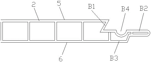
[0051] see Figure 1 ~ Figure 3 , Embodiment 1 includes A board 1 and B board 2.

[0052] After the A board 1 is installed, the front side 3 of the A board 1 faces outwards and is exposed, and a decorative structure can be arranged on the front side 3 of the A board 1; .

[0053] After the B-board 2 is installed, the front side 5 of the B-board 2 is outwardly exposed, and a decorative structure can be arranged on the front side 5 of the B-board 2; .

[0054] A concave butt end is provided on one side of the A board 1 . The concave butt end includes an upper edge end A1, a docking port A2 and a lower edge end A3.

[0055] The upper edge A1 and the lower edge A3 are fixed on one side of the A board 1 and can be integrally formed with the A board 1 . The upper edge A1 is close to the front face 3 of the A board 1, and the front face of the upper edge A1 is flush with the front face 3 of the A board 1, so that unevenness will not be caused.

[0056] The thickness of the upper ...

Embodiment 2

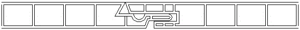
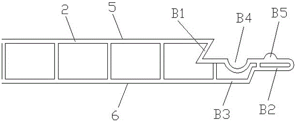
[0071] see Figure 4 ~ Figure 6 , Embodiment 2 On the basis of Embodiment 1, a clamping block B5 is fixedly arranged on the lower edge butt joint end B2, and a clamping slot A4 is opened on the upper edge end A1, and the clamping block B5 cooperates with the clamping slot A4. When the convex butt ends are spliced, the clamping block B5 and the clamping slot A4 are clamped.

Embodiment 3

[0073] see Figure 7 ~ Figure 9 , the difference between embodiment 3 and embodiment 1 is that when the concave butt end and the convex butt end are spliced, the upper edge butt end B1 and the upper edge end A1 are opposite but not in contact, and the gap between the two can be used for installation Construction and decoration materials such as stickers and metal strips. The gap can be formed by keeping the width of the upper edge end A1 constant and the upper edge butt end B1 retracting backward, so that the production of the product is simpler and the product firmness is better.


PUM


Abstract

The invention relates to a panel connection method applied in decoration panels and building materials. Panels include the panel A and the panel B. A U-shaped butt joint end is arranged on one side of the panel A and comprises an upper edge end, a butt joint opening and a lower edge end. An inverted-T-shaped butt joint end is arranged on one side of the panel B and comprises an upper edge butt joint end, a lower edge butt joint end and a base. A nailing position is arranged on the overlapped part of the lower edge butt joint end and the base. The width of the upper edge end is larger than that of the lower edge end. When the panel A and the panel B are spliced, the panel construction method includes the following steps that firstly, the panel B is placed at an installation position, then a screw is screwed in the nailing position of the panel B, and the panel B is fixed to the installation position through the screw; and secondly, the U-shaped butt joint end of the panel A is inserted in the inverted-T-shaped butt joint end of the panel B which is fixed well in the first step so that the panel A and the panel B can be spliced together. The panel construction method is low in rejection rate, long in service life, low in cost and good in effect.

Description

technical field [0001] The invention relates to a method for connecting panels, which is applied to decorative panels (wall surfaces, suspended ceilings, exterior wall facades, partitions, door panels, floors, etc.) )middle. Background technique [0002] In the prior art, the method of connecting decorative boards and building materials is divided into A board and B board, A board and B board as shown in Chinese patents owned by Zhejiang Pute Sunshine Board Co., Ltd. The shapes are the same, and they are spliced ​​and matched with each other. [0003] A concave butt end is provided on one side of the A board, and the concave butt end includes an upper edge end (that is, the lower bottom surface 33 in the Chinese patent No. 201220338846.2), a docking port (that is, the groove in the Chinese patent No. 31) and the lower edge (that is, the upper bottom surface 32 in the Chinese patent No. 201220338846.2). [0004] A convex butt end is provided on one side of the B board, and...

Claims


Application Information

Patent Timeline
Patent Type & Authority Applications(China)
IPC IPC(8): F16B5/07E04B1/61
CPCF16B5/07E04B1/61
Inventor 马再良钱智杰马剑
Owner TONGXIANG BOFAN DECORATIVE MATERIAL CO LTD
Why Eureka
Try Eureka