Charging landing gear, unmanned aerial vehicle, charging platform and unmanned aerial vehicle cruising and charging system

A charging platform and UAV technology, applied in battery circuit devices, current collectors, electric vehicles, etc., can solve the problems of limited application range and application methods, difficult wireless charging tasks for UAVs, and unoptimistic charging efficiency, etc. , to achieve high charging efficiency, stable reliability, high practicality, and flexible application methods

Active Publication Date: 2016-08-24
浙江国正安全技术有限公司
View PDF5 Cites 33 Cited by
  • Summary
  • Abstract
  • Description
  • Claims
  • Application Information

AI Technical Summary

Problems solved by technology

[0003] ① There is a charging interface on the drone body, and the charging work of the drone is completed by connecting to the charger. The drone using this scheme needs to take the drone back, and it needs to be in the strike stage for a long time. The scope of application and limited application methods;
[0004] ② Directly replace the battery of the UAV to achieve fast "charging", and the replaced battery is charged through a special charger, and this method must also take the UAV back and replace the battery manually, although compared with the previous one program, the efficiency has been improved, but its application scope and application methods are still limited;
[0005] ③Wireless charging technology is adopted, but this technology is not yet fully mature, and its charging efficiency is not optimistic. In the complex outdoor environment, it is difficult to ensure that the drone can complete the wireless charging task normally and effectively

Method used


Image

  • Charging landing gear, unmanned aerial vehicle, charging platform and unmanned aerial vehicle cruising and charging system
  • Charging landing gear, unmanned aerial vehicle, charging platform and unmanned aerial vehicle cruising and charging system
  • Charging landing gear, unmanned aerial vehicle, charging platform and unmanned aerial vehicle cruising and charging system

Examples


Embodiment Construction

[0032] All features disclosed in this specification, or steps in all methods or processes disclosed, may be combined in any manner, except for mutually exclusive features and / or steps.

[0033] Any feature disclosed in this specification (including any appended claims, abstract), unless otherwise stated, may be replaced by alternative features that are equivalent or serve a similar purpose. That is, unless expressly stated otherwise, each feature is one example only of a series of equivalent or similar features.

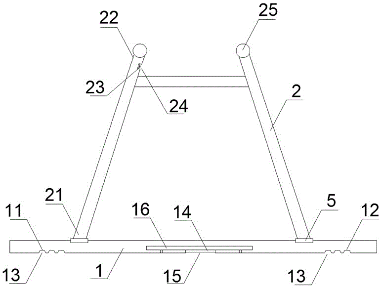
[0034] (1) Charging landing gear

[0035] Such as figure 1 As shown, the present invention proposes a charging landing gear suitable for unmanned aerial vehicles, the landing gear includes at least one crossbar 1 and at least one vertical pole 2, and the first end 21 of the vertical pole 2 is fixed on On the cross bar 1 , the second end 22 thereof is provided with a first connecting piece 25 for connecting the drone.

[0036]At least one first positive electrode ...


PUM


Abstract

The invention discloses a charging landing gear suitable for an unmanned aerial vehicle. A cross rod of the charging landing gear is provided with a plurality of charging contact parts, wherein a charging circuit module is also arranged in the cross rod; and adapting of a charging interface of the unmanned aerial vehicle can be directly finished through the landing gear. The invention discloses a landing gear-based unmanned aerial vehicle. The unmanned aerial vehicle can be electrically connected directly through the landing gear when charged; the unmanned aerial vehicle stops on a charging platform of the matched with the landing gear when needing to be charged; and the unmanned aerial vehicle can be charged through the charging platform. The invention further discloses the charging platform matched with the landing gear. Through the design which is simple in structure and low in cost, good contact of the charging contact parts is ensured. The invention further provides an unmanned aerial vehicle cruising and charging system based on the unmanned aerial vehicle and the charging platform. The charging platform can be searched for the unmanned aerial vehicle through a cloud management server; and a flight path is set for the unmanned aerial vehicle.

Description

technical field [0001] The invention relates to the field of unmanned aerial vehicle charging, especially a kind of charging landing gear suitable for unmanned aerial vehicles, a kind of unmanned aerial vehicle based on the landing gear, a charging platform matched with the landing gear, a charging platform based on the landing gear The above-mentioned unmanned aerial vehicle and the unmanned aerial vehicle endurance charging system of the charging platform. Background technique [0002] With the rapid development of the UAV industry, UAVs are becoming more and more widely used in people's production and life. At present, the rotor UAV mainly uses electricity as power, and the methods of UAV battery life and charging are generally as follows : [0003] ① There is a charging interface on the drone body, and the charging work of the drone is completed by connecting to the charger. The drone using this scheme needs to take the drone back, and it needs to be in the strike stage...

Claims


Application Information

Patent Timeline
Patent Type & Authority Applications(China)
IPC IPC(8): H02J7/00H02J50/80B64C25/06
CPCB64C25/06H02J7/00
Inventor 夏烬楚
Owner 浙江国正安全技术有限公司
Why Eureka
Try Eureka