AI technical title is built by PatSnap AI team. It summarizes the technical point description of the patent document.
A box-type substation, box body technology, applied in distribution substation, substation/switch layout details, substation/switchgear cooling/ventilation, etc.
Active Publication Date: 2018-09-21
HANGZHOU GUANGYIN POWER EQUIP IND CO LTD
View PDF3 Cites 0 Cited by
Summary
Abstract
Description
Claims
Application Information
AI Technical Summary
This helps you quickly interpret patents by identifying the three key elements:
Problems solved by technology
Method used
Benefits of technology
Problems solved by technology
However, such a heat dissipation method needs to continuously add water to the roof box, and the sealing performance requirements of the box and the water supply pipeline are high, and the load on the side wall of the box is increased, the structure is relatively complicated, and the practicability is not good.
In addition, the use of tap water for cooling will increase the air humidity around the substation, and there is a risk of electric leakage
Method used
Image
Click on the blue label to locate the original text in one second.
Reading with bidirectional positioning of images and text.
Examples
Embodiment 1
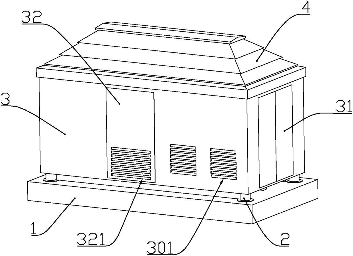
[0076] according to Figure 1 to Figure 13 As shown, this embodiment is a box-type substation, including a base 1 made of reinforced concrete, and a box 3 in the shape of a cuboid arranged above the base.
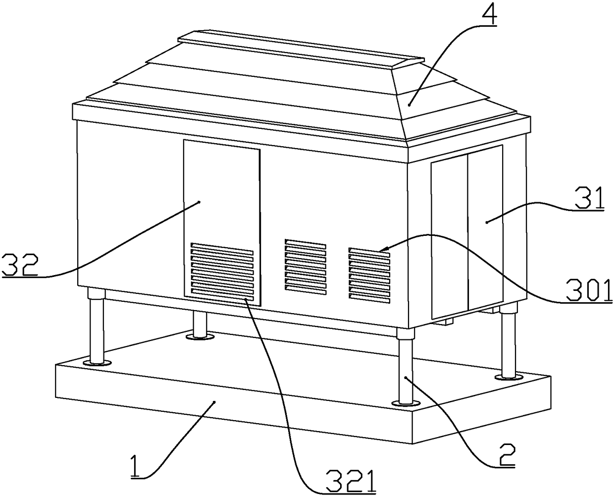
[0077]An electric push rod 2 arranged vertically is installed near the four vertices in the box, and the output rod of the electric push rod passes downward through the bottom plate at the lower end of the box body and is fixedly connected with the base.
[0078] A liquid level sensor (not shown) is installed on the lower end of the output rod or the base; the liquid level sensor and each electric push rod are respectively electrically connected to a control box, and the control box is installed inside the box.
[0079] When the liquid level sensor detects accumulated water, the control box controls the extension of the electric push rod to lift the tank, and the lifting height of the tank is proportional to the water level detected by the liquid level sensor.
[0080] The...
Embodiment 2
[0092] according to Figure 1 to Figure 13 As shown, this embodiment is a box-type substation, including a base 1 made of reinforced concrete, and a box 3 in the shape of a cuboid arranged above the base.
[0093] An electric push rod 2 arranged vertically is installed near the four vertices in the box, and the output rod of the electric push rod passes downward through the bottom plate at the lower end of the box body and is fixedly connected with the base.
[0094] A liquid level sensor (not shown) is installed on the lower end of the output rod or the base; the liquid level sensor and each electric push rod are respectively electrically connected to a control box, and the control box is installed inside the box.
[0095] When the liquid level sensor detects accumulated water, the control box controls the extension of the electric push rod to lift the tank, and the lifting height of the tank is proportional to the water level detected by the liquid level sensor.
[0096] Th...
Embodiment 3
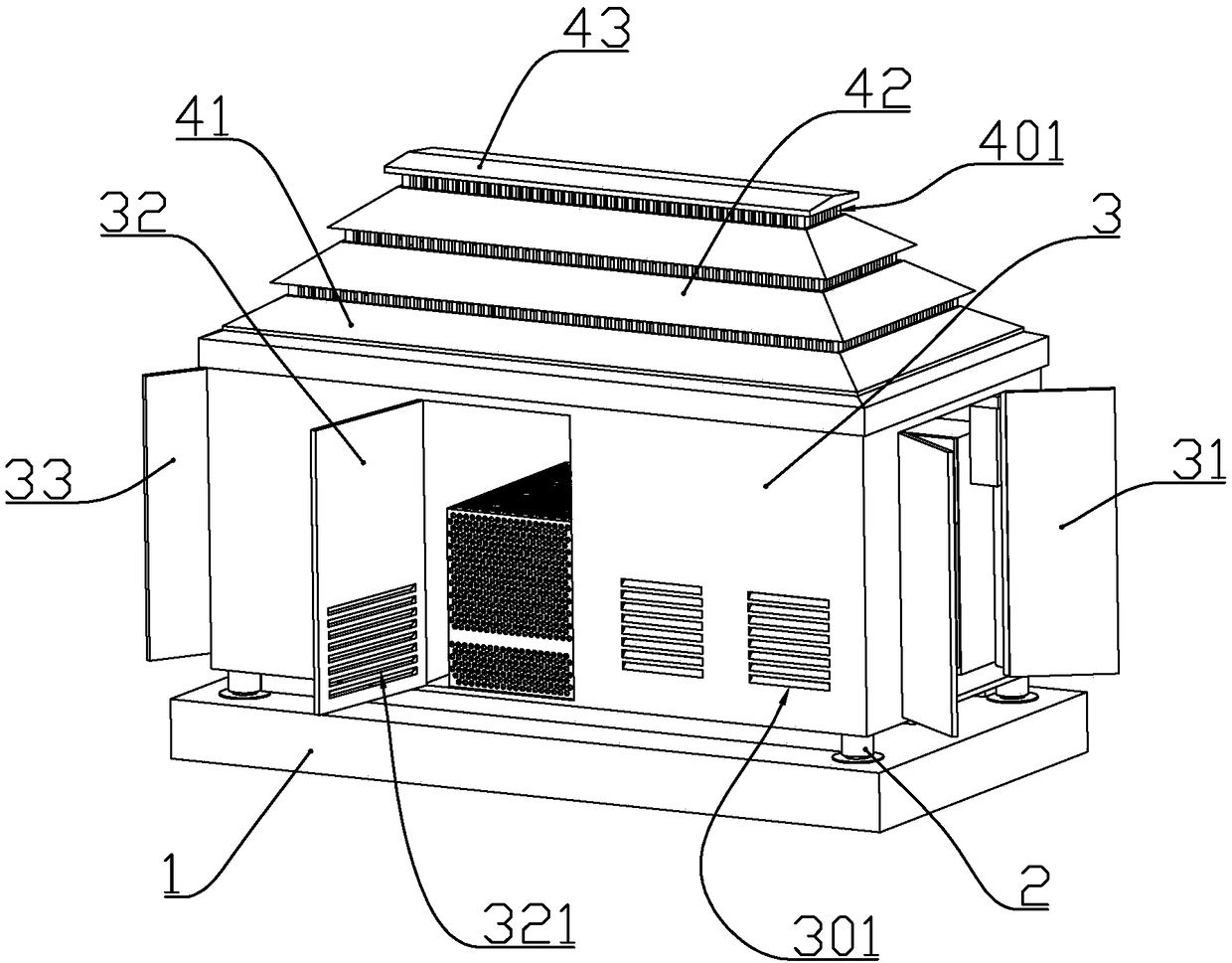
[0127] This embodiment also makes the following improvements on the basis of Embodiment 2: more than one middle top cover 42 is installed between the lower top cover and the upper top cover, and the middle top cover includes a rectangular frame shape The ventilation wall, and the slope wall fixedly connected to the upper end of the ventilation wall; the outer end of the slope wall forms an extension wall located outside the ventilation wall, and the ventilation wall is uniformly formed with air outlets, and the air outlets are longitudinal The provided bar-shaped opening; the outer circumference of the ventilation wall of the middle roof matches the inner circumference size of the slope wall of the lower roof, or matches the inner circumference size of the slope wall of another middle roof located below it; The lower outer wall of the ventilation wall on the middle roof and the upper roof is also formed with a support step 403 for supporting the slope wall below;
[0128] When...
PUM
Abstract
The invention discloses a box-type transformer substation. The box-type transformer substation comprises a substrate and a box body, wherein the box body is arranged above the substrate; a top cover is connected above the box body; the top cover comprises a lower top cover fixedly connected above the box body, and an upper top cover installed on the lower top cover; the lower top cover comprises a longitudinal wall, and a slope wall fixedly connected with an upper end of the longitudinal wall; an external end of the slope wall is formed into an extension wall positioned outside the longitudinal wall; the upper top cover comprises a ventilating wall having a rectangular frame form, and an upper sealing plate fixedly connected with the upper end of the ventilating wall; the external end of the upper sealing plate is formed into the extension wall outside the ventilating wall; air vents are uniformly formed in the ventilating wall; axial flow fans are installed at positions, corresponding to a transformer chamber and a low voltage chamber, above the box body; top cover pushing rods which are longitudinally arranged are further installed at the positions, corresponding to two end portions of the upper sealing plate, above the top cover; and output rods of the top cover pushing rods are fixedly connected with the upper sealing plate of the upper top cover. The box-type transformer substation disclosed by the invention is compact in structure, reasonable in design, convenient in construction and good in heat dissipation effect.
Description
technical field [0001] The invention belongs to the field of electric equipment, and in particular relates to a structure of a box-type substation. Background technique [0002] The Chinese patent with the document number CN204271514U discloses a waterproof box-type substation, which solves the problem that when natural disasters such as floods and heavy rains occur, a large amount of water will enter the box-type substation with a relatively high water level, which will cause damage to large-scale box-type substations. damage, the main point of the technical solution is to set up a lifting mechanism so that the power distribution equipment can be lifted up and down, and at the same time, the box is equipped with a stretching mechanism, and the height of the box can also be raised when the power distribution equipment is lifted, so that the water will not touch it. Power distribution equipment, to protect the power distribution equipment, the box can be stretched to ensure t...
Claims
Application Information
Patent Timeline
Application Date:The date an application was filed.
Publication Date:The date a patent or application was officially published.
First Publication Date:The earliest publication date of a patent with the same application number.
Issue Date:Publication date of the patent grant document.
PCT Entry Date:The Entry date of PCT National Phase.
Estimated Expiry Date:The statutory expiry date of a patent right according to the Patent Law, and it is the longest term of protection that the patent right can achieve without the termination of the patent right due to other reasons(Term extension factor has been taken into account ).
Invalid Date:Actual expiry date is based on effective date or publication date of legal transaction data of invalid patent.

