Indicative power supply device

A power supply device and indication technology, which is applied in the direction of electromechanical devices, coupling devices, parts of connecting devices, etc., can solve the problems of inability to realize automatic implementation, inability to guarantee reliability and stability of electrical joints, etc.

Inactive Publication Date: 2016-09-28
龚云新
View PDF3 Cites 9 Cited by
  • Summary
  • Abstract
  • Description
  • Claims
  • Application Information

AI Technical Summary

Problems solved by technology

[0002] Reliable and convenient electrical connection is required between some electrical equipment and power supply equipment; however, in the electrical connection of some existing power supply equipment, it cannot guarantee the reliability and stability of the electrical connection; or, in realizing a more reliable electrical connection Connected power supply equipment, which cannot be implemented automatically
And, more importantly, there is no way to ensure that the position of the socket and the plunger is locked after being engaged, while mechanically ensuring the stable engagement of the socket and the plunger before engagement and the position locking after engagement.

Method used


Image

  • Indicative power supply device

Examples


Embodiment Construction

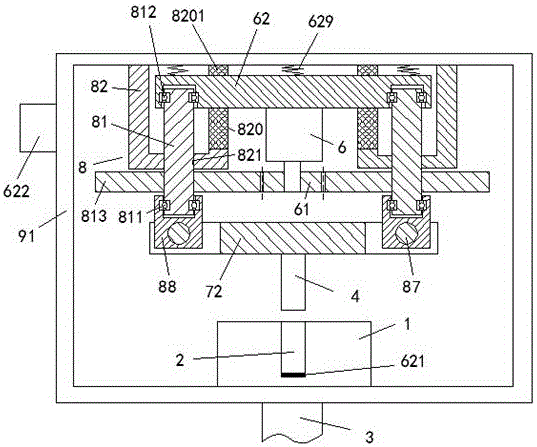
[0007] Combine below figure 1 The present invention will be described in detail.

[0008] An indicating power supply device according to an embodiment includes a casing 91, a power supply socket device 1 arranged on the lower side wall of the casing 91, and a socket device 1 arranged on the upper side wall of the casing 91. The power plug device, the power supply jack device 1 includes a power supply cable 3 and a power supply hole 2 for electrical connection with the power plug device, and the power plug device includes an upper side wall connected to the housing 91 Two jacking screw assemblies 8 fixedly connected, the two jacking screw assemblies 8 are arranged symmetrically with respect to the longitudinal axis of the housing 91 and each includes: fixed on the upper side wall of the housing 91 The threaded fixing sleeve 82, the pressing screw rod 81 threadedly engaged with the threaded hole 821 in the lower end wall of the threaded fixing sleeve 82, is located under the th...


PUM


Abstract

The invention provides an indicative power supply device comprising a shell (91), a power supply jack device (1) which is arranged on the lower side wall of the shell (91) and a power utilization plug device which is arranged on the upper side wall of the shell (91). The power supply jack device (1) comprises a power supply cable (3) and a power supply hole (2) which is electrically connected with the power utilization plug device. The power utilization plug device comprises two abutting screw rod components (8) which are fixedly connected with the upper side wall of the shell (91). The two abutting screw rod components (8) are symmetrically arranged about the longitudinal axis of the shell (91), and each abutting screw rod component (8) comprises a threaded fixing sleeve (82) which is fixed on the upper side wall of the shell (91) and an abutting screw rod (81) which is matched with the threaded hole (821) in the lower end wall of the threaded fixing sleeve (82) in a threaded way.

Description

technical field [0001] The invention relates to the field of power supply equipment, in particular to an indicating power supply device. Background technique [0002] Reliable and convenient electrical connection is required between some electrical equipment and power supply equipment; however, in the electrical connection of some existing power supply equipment, it cannot guarantee the reliability and stability of the electrical connection; or, in realizing a more reliable electrical connection In connected power supply equipment, it cannot be implemented automatically. Moreover, more importantly, it is impossible to guarantee the position locking after the socket and the insertion rod are engaged, and at the same time mechanically ensure the stable engagement of the insertion hole and the insertion rod before engagement and the position locking after engagement. Contents of the invention [0003] The purpose of the present invention is to provide an indicating power sup...

Claims


Application Information

Patent Timeline
Patent Type & Authority Applications(China)
IPC IPC(8): H01R13/629H01R13/639H02K7/116
CPCH01R13/629H01R13/639H02K7/116
Inventor 龚云新
Owner 龚云新
Why Eureka
Try Eureka