Image defogging method

An image and maximum pixel technology, applied in image enhancement, image data processing, instruments, etc., can solve problems such as not being particularly perfect, and achieve the effects of improved accuracy, high fidelity, and improved real-time performance

Inactive Publication Date: 2016-10-05
HOHAI UNIV
View PDF1 Cites 7 Cited by
  • Summary
  • Abstract
  • Description
  • Claims
  • Application Information

AI Technical Summary

Problems solved by technology

At present, the methods of image defogging proposed by scholars at home and abroad are not particularly perfect, and need to be improved and improved urgently, especially how to improve the real-time performance and fidelity of defogging processing is the key to solving the problem of defogging

Method used


Image

  • Image defogging method
  • Image defogging method
  • Image defogging method

Examples


Embodiment Construction

[0033] The technical solution of the present invention will be described in detail below in conjunction with the accompanying drawings.

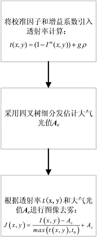
[0034] Such as figure 1 As shown, an image defogging method includes the following steps:

[0035] Step 1. Calculate the transmittance of the foggy image:

[0036] t(x,y)=(1-I m (x,y))+gρ (1)

[0037] In formula (1), t(x,y) is the transmittance, (x,y) is the pixel coordinate, ρ is the calibration factor, and the value of ρ is usually in [0.8,1]. In this embodiment, ρ= 0.9, g is the gain constant:

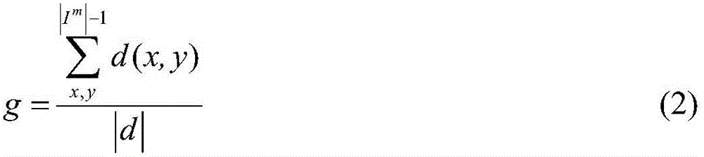
[0038] g = X x , y | I m | - 1 d ( x , y ) | d | - - - ( 2 )

[0039] In formula (2), |I m | And |d| are I respectively m And the total number of pixels of d, corresponding to I m And d:

[0040] I m ( x , y ) = m i n c A { R , G , B } I c ( x , y ) - - - ( 3 )

[0041] d(x,y)=I m (x,y)-I d (x,y) ...


PUM


Abstract

The invention discloses an image defogging method. The method uses a new transmittance estimation method to replace a soft matting method, the transmittance is solved through gain intervention on the three-primary color channel minimum component for a foggy image, on the premise of avoiding halation and fast effects, the approximate dark channel image intensity is solved quickly, the real-time performance of the algorithm is thus improved, a quad-tree subdivision method is used for estimating the atmospheric light value, the atmospheric light value precision is improved, and finally, through the transmittance and the atmospheric light value, defogging is carried out on multiple images. The method of the invention improves the real-time performance of defogging and the fidelity of a defogged image.

Description

Technical field [0001] The invention belongs to the technical field of digital image processing and machine vision, and particularly relates to an image defogging method. Background technique [0002] With the development of science and technology and the improvement of people's living standards, more and more visual systems are used in real life, such as: monitoring systems, intelligent transportation systems, etc., and the quality and demand of human life are gradually improved. These application systems are in line with human life. It is closely related and directly image human life. [0003] The reduced air quality and reduced visibility have had a great impact on people's lives and industrial development. Because the light is absorbed and scattered by the turbid medium, pictures taken in bad weather outdoors reduce the intensity of the light, resulting in a change in the intensity of the light received by the optical sensor, and ultimately resulting in a decrease in color fid...

Claims


Application Information

Patent Timeline
Patent Type & Authority Applications(China)
IPC IPC(8): G06T5/00
CPCG06T5/003
Inventor 李昌利平学伟陈琳
Owner HOHAI UNIV
Why Eureka
Try Eureka