A double-end mechanical seal with an I-shaped sealing cavity

A technology of mechanical sealing and cavity sealing, which is applied in the direction of engine sealing, mechanical equipment, engine components, etc., and can solve problems such as difficulty in ensuring safe production, increasing reliability requirements of the oil sealing system, and unreliability of the oil sealing system

Inactive Publication Date: 2018-06-12
韩乐工
View PDF5 Cites 0 Cited by
  • Summary
  • Abstract
  • Description
  • Claims
  • Application Information

AI Technical Summary

Problems solved by technology

The so-called oil sealing system is usually composed of a sealing oil tank, an oil sealing pump, and an oil sealing circulation pipeline to provide an oil sealing system. The so-called zero leakage means that the sealing oil pressure is slightly higher than the pressure of the sealed medium to prevent the sealed medium Leakage, and a small amount of sealing oil leakage is allowed, which not only increases the cost of mechanical seal operation, but also increases the reliability requirements of the sealing oil system. The sealing oil system is unreliable, and it is also difficult to guarantee safe production. The system can also make the double-end mechanical seal achieve zero leakage, safe, reliable, and long-life operation. This is undoubtedly an important issue to be solved by mechanical seal technology

Method used


Image

  • A double-end mechanical seal with an I-shaped sealing cavity
  • A double-end mechanical seal with an I-shaped sealing cavity
  • A double-end mechanical seal with an I-shaped sealing cavity

Examples


Embodiment Construction

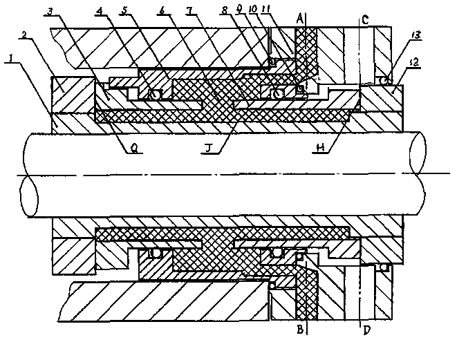
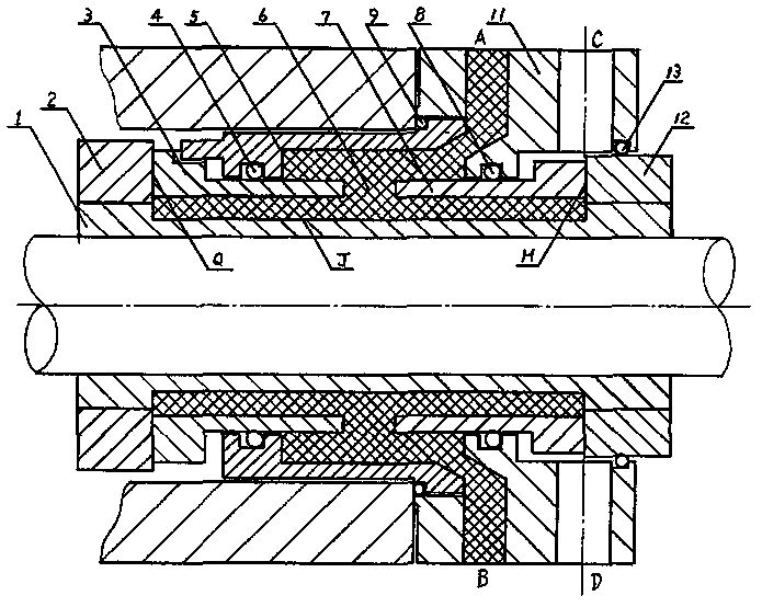
[0032] Below according to accompanying drawing among the present invention, the concrete content of the present invention is carried out necessary description:

[0033] figure 1As shown, the grid portion in the plugging cavity 6 refers to the mud-like filler filled in the I-shaped plugging cavity. In the figure, the moving ring end face and the front static ring The end surface of 3 constitutes the sealing surface Q of the front end, and the front end is in the sealed medium. In the figure, the end surface of the moving ring in the rear end moving ring structure 12 sleeved on the shaft sleeve 1 and the end face of the rear end static ring 7 constitute a place The rear end sealing surface H in the external environment, and the mud-like packing tightly wrapped on the ring groove surface of the shaft sleeve 1 constitutes the radial annular sealing surface J, and the front static ring sealing ring 4 installed on the sealing sleeve 5 is both Prevent the sealed medium from entering...


PUM


Abstract

The invention provides a double-end-face mechanical seal with an H-shaped plugging cavity. As shown in the figure, the structure with the H-shaped plugging cavity 6 is formed by a shaft sleeve 1, a front end moving ring structure 2, a front end fixed ring 3, a sealing sleeve 5, a rear end fixed ring 7, a rear end moving ring structure 12, a pressing cover 11, auxiliary sealing elements 4, 8 and 10 and the like, thus, concave moving sealing structures of the front end face sealing face Q, the rear end face sealing face H and the radial ring-shaped sealing face J are formed, and therefore the double-end-face mechanical seal with the H-shaped plugging cavity can achieve zero leakage when an oil sealing system is not used, and long service life and safety operation can be achieved.

Description

technical field [0001] The invention relates to a mechanical seal, in particular to a double-end mechanical seal with an I-shaped sealing cavity. Background technique [0002] With the increasingly stringent requirements for environmental protection, in order to meet these requirements in the petrochemical industry, higher requirements are put forward for the mechanical seals used on equipment that transport toxic, harmful, high-temperature, flammable and explosive media, that is, to use The double-end mechanical seal is also equipped with an oil sealing system to ensure that the sealed medium does not leak, that is, to achieve zero leakage, and it can also run safely and reliably with a long life. The so-called oil sealing system is usually composed of a sealing oil tank, an oil sealing pump, and an oil sealing circulation pipeline to provide a sealing oil system. The so-called zero leakage means that the sealing oil pressure is slightly higher than the pressure of the seal...

Claims


Application Information

Patent Timeline
Patent Type & Authority Patents(China)
IPC IPC(8): F16J15/34
Inventor 韩乐工
Owner 韩乐工
Why Eureka
Try Eureka