Parachute throwing device for unmanned aerial vehicle and unmanned aerial vehicle

A technology of drones and paracords, applied in the field of drones, can solve the problems of no multiple use, high cost of use, and difficulty in wide application in large quantities

Active Publication Date: 2016-12-07
北京韦加科创技术有限公司
View PDF7 Cites 6 Cited by
  • Summary
  • Abstract
  • Description
  • Claims
  • Application Information

AI Technical Summary

Problems solved by technology

[0003] At present, most of the parachute throwers used in small UAV systems developed around the world are pyrotechnic items, which are prohibited for military use. They are difficult to popularize in civilian use, expensive, and prohibited from being stored, transported and installed as civilian products. Although it is simple, it is difficult to be widely used in large quantities for civilian use; moreover, this parachute thrower is disposable and has no possibility of multiple uses, so the cost of use is quite high, and civilian use cannot be popularized at all.

Method used


Image

  • Parachute throwing device for unmanned aerial vehicle and unmanned aerial vehicle
  • Parachute throwing device for unmanned aerial vehicle and unmanned aerial vehicle
  • Parachute throwing device for unmanned aerial vehicle and unmanned aerial vehicle

Examples


Embodiment 1

[0028] The UAV parachute throwing device provided in this embodiment includes an umbrella rope pin, a housing, a drive mechanism, a transmission mechanism and a clamping mechanism for clamping the umbrella rope pin arranged inside the housing; The output shaft of the driving mechanism is connected with the transmission mechanism for driving the clamping mechanism to rotate, and the transmission mechanism is connected with the clamping mechanism for driving the clamping mechanism to release the umbrella rope pin; An opening is provided on the housing so that the paracord pin can pass through the opening and disengage from the clamping mechanism.

[0029] The UAV parachute throwing device provided in this embodiment, when the parachute needs to be connected to the clamping mechanism, the parachute pin connected with the parachute is clamped in the housing by the clamping mechanism, thereby fixing the parachute on the parachute throwing device When the parachute needs to be throw...

Embodiment 2

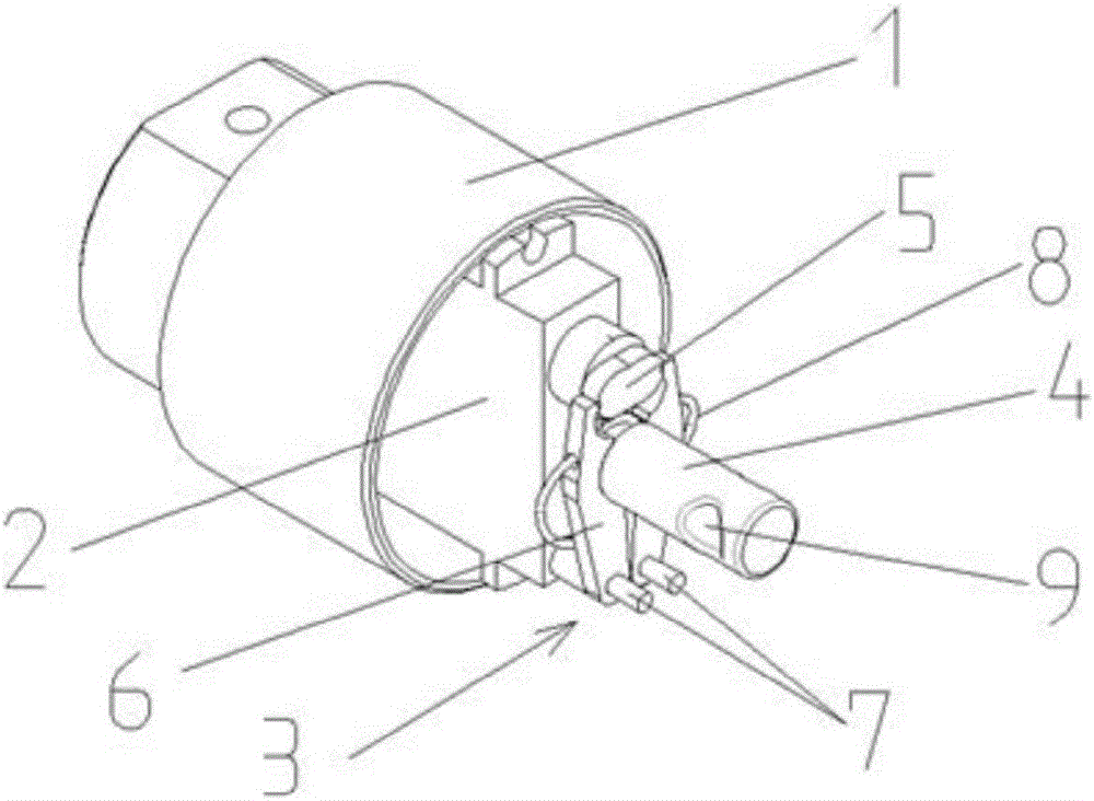
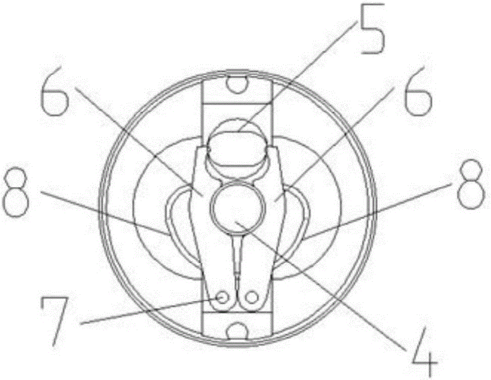
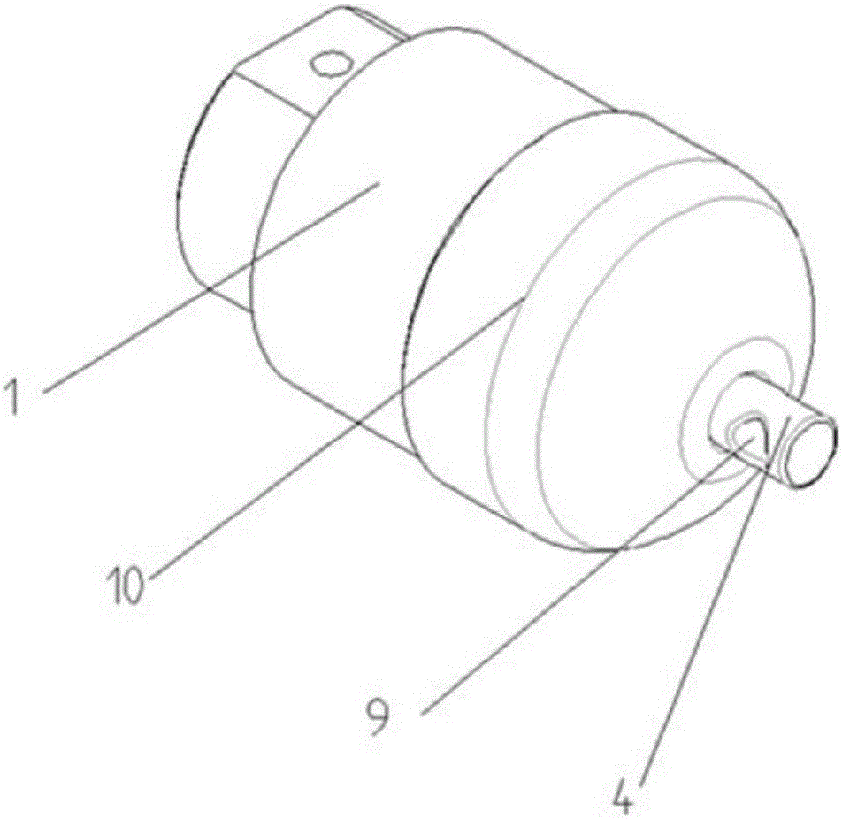
[0031] Such as Figures 1 to 4 As shown, the UAV parachute throwing device provided in this embodiment includes a parachute pin 4, a housing 1, a drive mechanism 2 arranged inside the housing 1, a transmission mechanism, and a parachute for clamping the parachute. The clamping mechanism 3 of the pin 4; the output shaft of the driving mechanism 2 is connected with the transmission mechanism for driving the rotation of the clamping mechanism 3, and the transmission mechanism is connected with the clamping mechanism 3 for driving The clamping mechanism 3 releases the parachute pin 4 ; an opening is provided on the housing 1 so that the parachute pin 4 passes through the opening and detaches from the clamping mechanism 3 .

[0032] The driving mechanism 2 wherein is preferably a servo steering gear, the transmission mechanism includes a cam 5, and the clamping mechanism 3 includes a caliper shaft 7, a snap ring 8 and a caliper that rotates around the caliper shaft 7; the caliper i...

Embodiment 3

[0039] The UAV provided in this embodiment includes a body, a parachute, and the UAV parachute device described in the first or second embodiment above. Rope pin connection.


PUM


Abstract

The invention relates to a parachute throwing device for an unmanned aerial vehicle and the unmanned aerial vehicle. The parachute throwing device comprises a parachute cord pin, a shell, a driving mechanism, a transmission mechanism and a clamping mechanism, wherein the driving mechanism, the transmission mechanism and the clamping mechanism are arranged in the shell; the clamping mechanism is used for clamping the parachute cord pin tightly; the output shaft of the driving mechanism is connected with the transmission mechanism; the driving mechanism is used for driving the clamping mechanism to rotate; the transmission mechanism is connected with the clamping mechanism, and used for driving the clamping mechanism to release the parachute cord pin; an opening is formed in the shell, so that the parachute cord pin can penetrate through the opening and be disengaged from the clamping mechanism. Therefore, the parachute cord pin can be released timely and conveniently, that is, a parachute cord can be disengaged from the unmanned aerial vehicle timely and conveniently.

Description

technical field [0001] The invention relates to the technical field of unmanned aerial vehicles, in particular to an unmanned aerial vehicle parachuting device and an unmanned aerial vehicle. Background technique [0002] The parachute throwing device is indispensable in the UAV system, which is mainly manifested in the following aspects: On the one hand, after the UAV system performs the recovery procedure, if the parachute is opened in the air and the parachute is abnormal, it will generally trigger the parachute The recovery fails. At this time, the parachute throwing system triggers the work, the parachute thrower mechanism moves, and the problematic parachute is discarded, so that the UAV enters the normal flight stage again, avoiding the failure of parachute recovery, and allowing the UAV system to have a normal forced landing condition , forced landing, reducing the loss caused by abnormal parachuting. On the other hand, at the end of the parachute recovery of the UA...

Claims


Application Information

Patent Timeline
IPC IPC(8): B64D17/38B64D17/80
CPCB64D17/38B64D17/80
Inventor 李志宁
Owner 北京韦加科创技术有限公司
Why Eureka
Try Eureka