Method for non uniformity correction of range finding of array push-scan type laser radar

A non-uniformity correction and laser radar technology, which is applied in the direction of measuring devices, electromagnetic wave reradiation, radio wave measurement systems, etc., to achieve the effects of convenient calculation, elimination of distance measurement differences, and improvement of applicability

Active Publication Date: 2017-01-04
ACAD OF OPTO ELECTRONICS CHINESE ACAD OF SCI
View PDF5 Cites 36 Cited by
  • Summary
  • Abstract
  • Description
  • Claims
  • Application Information

AI Technical Summary

Problems solved by technology

[0005] The above method is to correct the non-uniformity of ranging by hardware means, but it is necessary to adjust the device gain parameters during data collection. The correction results are only valid for the current data, and the uniformity correction needs to be performed again for each test.

Method used


Image

  • Method for non uniformity correction of range finding of array push-scan type laser radar
  • Method for non uniformity correction of range finding of array push-scan type laser radar
  • Method for non uniformity correction of range finding of array push-scan type laser radar

Examples


Embodiment Construction

[0018] Certain embodiments of the invention will be described more fully hereinafter with reference to the accompanying drawings, in which some, but not all embodiments are shown. Indeed, various embodiments of the invention may be embodied in many different forms and should not be construed as limited to these set forth embodiments; rather, these embodiments are provided so that this invention will satisfy applicable legal requirements.

[0019] In order to make the object, technical solution and advantages of the present invention clearer, the present invention will be described in further detail below in conjunction with specific embodiments and with reference to the accompanying drawings.

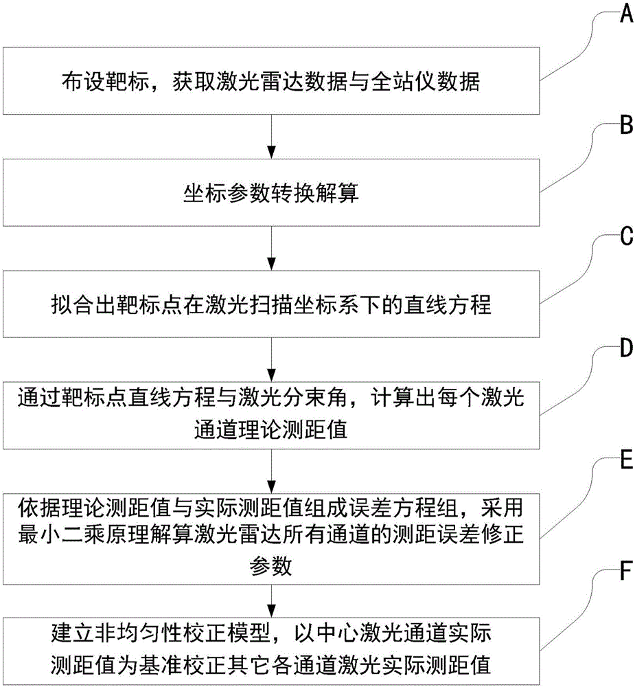
[0020] An embodiment of the present invention provides a non-uniformity correction method for array push-broom laser radar ranging, figure 1 It is a flowchart of a method for correcting non-uniformity of array push-broom laser radar ranging according to an embodiment of the present inve...


PUM


Abstract

The invention provides a method for non uniformity correction of range finding of an array push-scan type laser radar. An array push-scan type laser radar with N laser channels are used for detecting a target plate, the relative position of the array push-scan type laser radar and the target plate is changed, and the target plate is detected for M times, so laser radar data and total station data corresponding to each laser channel are obtained. By carrying out operation like coordinate transformation, a non uniformity correction model is established, and an actual range finding value of any one laser channel is used as a reference correction value to correct actual range finding values of other laser channels.

Description

technical field [0001] The invention relates to the technical field of laser radar in the optoelectronics industry, in particular to an array push-broom laser radar ranging non-uniformity correction method. Background technique [0002] With the rapid development of lidar technology, array pushbroom lidar has become a research hotspot at home and abroad due to its unique advantages of high precision and fast imaging. The array push-broom lidar can obtain the position information of multiple points per pulse, and only needs to scan one-dimensionally along the flight direction to complete the regional imaging, which greatly improves the imaging speed. There are great technical advantages and broad application prospects in the field of imaging. [0003] Different from the unit detection lidar, the array pushbroom type lidar is in the process of laser emission, echo reception and echo detection respectively. The response sensitivity of the array push-broom laser radar is incon...

Claims


Application Information

Patent Timeline
Patent Type & Authority Applications(China)
IPC IPC(8): G01S7/497G01S17/08
CPCG01S7/497G01S17/08
Inventor 李传荣朱晓玲周梅黎荆梅张慧静马莲陈玖英吴昊昊李伟
Owner ACAD OF OPTO ELECTRONICS CHINESE ACAD OF SCI
Why Eureka
Try Eureka