Point condensing device

The technology of a light concentrating device and a light emitting device, which is applied in the field of light concentrating, can solve the problems of reducing light irradiance, uneven irradiance, and reduced service life of LED components, and achieves the goals of improving utilization rate, reducing cost, and high uniformity Effect

Pending Publication Date: 2017-01-25
GUANGDONG AOPUTE TECH CO LTD
View PDF15 Cites 2 Cited by
  • Summary
  • Abstract
  • Description
  • Claims
  • Application Information

AI Technical Summary

Problems solved by technology

[0002] In the field of light sources for industrial use, in order to obtain good illuminance, it is usually necessary to gather the light emitted by the illuminant into a point shape, but the existing point-shaped light-gathering device has a relatively poor light-gathering effect (that is, light utilization efficiency). The illuminance is not enough, and the irradiance of the light will be uneven in the target area irradiated by the point-shaped concentrating device
Therefore, in order to solve the situation of insufficient illumination of the light source, the method of increasing the power of the light-emitting element (such as the LED element) is generally adopted, so that the LED element is in a full-load or close to full-load working state. However, in such a working state, the LED element uses The lifespan will be significantly reduced, and the problem of uneven irradiance is still not well resolved; in order to solve the problem of uneven irradiance, a layer of film-like parts that can evenly scatter light can be added at the position where the light is emitted to improve some Uniformity of irradiance, but adding such film-like parts will reduce the light transmittance and reduce the irradiance of light
Therefore, the high irradiance and high uniformity of light in the concentrating device in the prior art cannot be achieved at the same time

Method used


Image

  • Point condensing device
  • Point condensing device

Examples


Embodiment Construction

[0014] The present invention will be described in further detail below in conjunction with the specific embodiments and the accompanying drawings, but the embodiments of the present invention are not limited thereto.

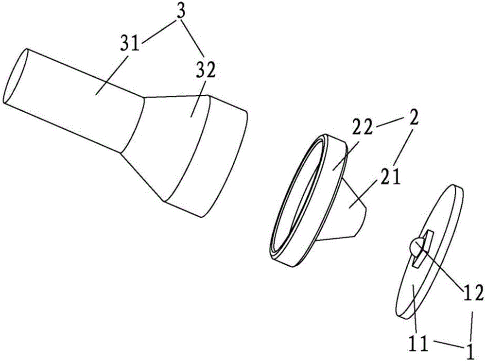
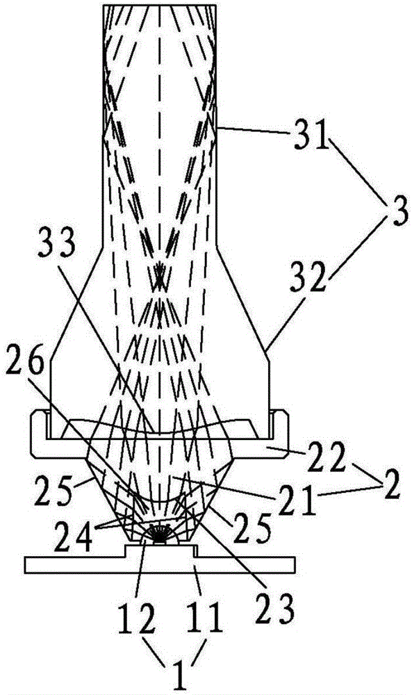
[0015] Such as figure 1 and 2 As shown, a point-like concentrating device includes a light emitting device 1, a converging lens 2 and a light guide lens 3, the concentrating lens 2 is installed on the light emitting device 1, the conduit lens is installed on the concentrating lens 2, the concentrating lens 2 and the The light guide lens 3 is a rotating body, and the central axes of the condenser lens 2 and the light guide lens 3 are on the same straight line. The optical disc 31 and the light guide column 32 integrally connected with the guide disc 31 , the light guide column 32 has a cylindrical structure, and the bottom of the guide disc 31 is provided with a first refraction curved surface 33 .

[0016] Preferably, the condensing lens 2 includes a condensin...


PUM


Abstract

The invention belongs to the technical field of condensation, and particularly relates to a point condensing device. The device comprises a light emitting device, a condensing lens and a light guide lens, wherein the condensing lens is arranged above the light emitting device; the light guide lens is arranged on the condensing lens; the condensing lens and the light emitting device are rotors, and center axes of the condensing lens and light guide device are arranged on the same line; the light guide lens comprises a light guide disc and a light guide column which is connected with the light guide disc into a whole; and light emitted from the light emitting device sequentially passes through the condensing lens and the light guide lens and is uniformly exported in point shape. The light emitting device, the condensing lens and the light guide lens are matched, so that a light emitting element with relatively small power can achieve the effects of high irradiance and high uniformity; and the device is formed by simple parts, so that cost can be greatly reduced.

Description

technical field [0001] The invention belongs to the field of light concentrating technology, in particular to a point-shaped light concentrating device. Background technique [0002] In the field of light sources for industrial use, in order to obtain good illuminance, it is usually necessary to gather the light emitted by the illuminant into a point shape, but the existing point-shaped light-gathering device has a relatively poor light-gathering effect (that is, light utilization efficiency). As a result, the illuminance is insufficient, and the phenomenon of uneven irradiance of light will appear in the target area irradiated by the point-like concentrating device. Therefore, in order to solve the problem of insufficient illumination of the light source, the method of increasing the power used by light-emitting elements (such as LED elements) is generally adopted, so that the LED elements are in a full-load or close to full-load working state. The lifespan will be signifi...

Claims


Application Information

Patent Timeline
Patent Type & Authority Applications(China)
IPC IPC(8): F21K9/20F21K9/69F21V5/04F21V19/00F21Y115/10
CPCF21V5/04F21V19/001
Inventor 卢盛林
Owner GUANGDONG AOPUTE TECH CO LTD
Why Eureka
Try Eureka