Gas generator

A gas generator and gas generation technology, applied in the direction of gas generating devices, chemical instruments and methods, vehicle parts, etc., can solve the problems of manufacturing cost pressure, increased number of parts, and deteriorated workability

Inactive Publication Date: 2017-02-22
NIPPON KAYAKU CO LTD
View PDF10 Cites 3 Cited by
  • Summary
  • Abstract
  • Description
  • Claims
  • Application Information

AI Technical Summary

Problems solved by technology

[0016] However, in order to make the fracture strength of each sealing tape covered with a plurality of gas passage holes (including the above-mentioned gas ejection port and gas communication hole) different, as in the above-mentioned International Publication No. 2005 / 014345 and the above-mentioned Japanese Patent Laid-Open In the case of using a plurality of sealing tapes of different specifications (that is, different thicknesses) as disclosed in Publication No. 2000-335361, there is a problem that the number of parts increases and the manufacturing cost is put under pressure
[0017] In order to prevent this situation, it is effective to make a difference in the number of laminated sheets of the seal tape as disclosed in the above-mentioned Japanese Patent Application Laid-Open No. 2002-96705, but since the seal tape is an adhesive member, it is positioned at the The work of pasting the predetermined part of the gas generator is accompanied by a considerable degree of difficulty, especially in the case where the sealing tape is laminated without any careful design, the workability is greatly deteriorated, and other problems such as a decrease in productivity will inevitably occur

Method used


Image

  • Gas generator
  • Gas generator
  • Gas generator

Examples


Embodiment approach 1

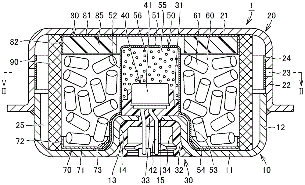
[0054] figure 1 It is a schematic diagram of the gas generator in Embodiment 1 of this invention. First, refer to the figure 1 The structure of the gas generator of this embodiment is demonstrated.

[0055] Such as figure 1 As shown, the gas generator 1 of this embodiment has a short and substantially cylindrical casing with both ends in the axial direction covered, and is configured to accommodate components as internal components in a storage space provided inside the casing. The holding part 30, the igniter 40, the cup member 50, the ignition agent 56, the gas generating agent 61, the lower support member 70, the upper support member 80, the cushion material 85, the filter 90, and the like. In addition, a combustion chamber 60 that mainly accommodates the gas generating agent 61 in the above-mentioned internal structural parts is provided in the storage space provided inside the casing.

[0056] The short-dimensioned substantially cylindrical housing includes a lower si...

no. 1 approach example )

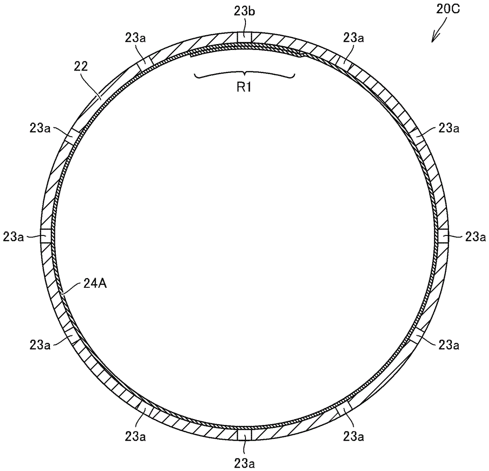
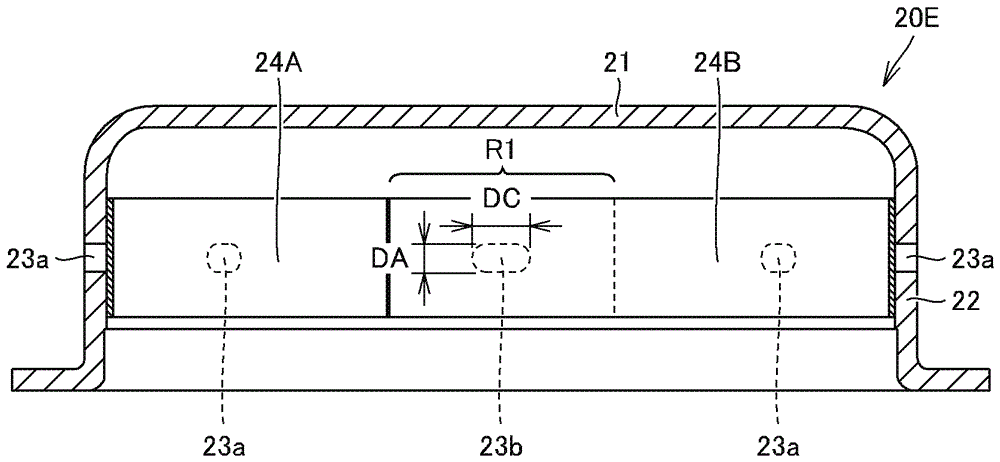
[0112] figure 2 and image 3 It is an end view and a cross-sectional view of an upper side shell related to the first example. First, refer to these figure 2 and image 3 Explain in detail the example of the first plan.

[0113] Such as figure 2 and image 3 As shown, the upper side shell 20A has a structure in which a plurality of strip-shaped sealing tapes 24A, 24B are attached to the inner peripheral surface of the peripheral wall portion 22 provided with a plurality of gas ejection ports 23a, 23b. The gas ejection ports 23a, 23b are covered with these strip-shaped multi-sheet seal tapes 24A, 24B.

[0114] The total number of gas ejection ports 23a, 23b is 12, and they are provided so as to be scattered at different positions in the circumferential direction of the peripheral wall portion 22 of the upper side shell 20A. More specifically, a total of 12 gas ejection ports 23 a , 23 b have the same opening area (that is, opening diameter) and are arranged in a row a...

no. 2 approach example )

[0121] Figure 4 It is an end view of the upper side case related to the second example. Next, refer to the Figure 4 Explain in detail the second example. In addition, when the second example is compared with the above-mentioned first example, only the structure of the overlapping region is different.

[0122] Such as Figure 4 As shown, the upper side shell 20A1 is the same as the upper side shell 20A related to the above-mentioned first embodiment, and has a structure as follows: The plurality of strip-shaped sealing tapes 24A, 24B cover the plurality of gas ejection ports 23a, 23b with these strip-shaped multi-sheet sealing tapes 24A, 24B.

[0123] Here, in the second example, unlike the above-mentioned first example, one of the pair of end portions in the extending direction of the sealing tape 24A is covered by the sealing tape 24B, and the other end portion is to be sealed. One of the pair of ends in the extending direction of the seal tape 24B is covered with the ...


PUM


Abstract

A gas generator comprises a cylindrical partition wall section (22) provided with gas passage holes (23a, 23b) through which gas generated by the combustion of a gas generation agent passes. Two band-shaped seal tapes (24A, 24B) are continuously adhered to the partition wall section (22) so that: the direction of extension of each of the seal tapes (24A, 24B) coincides with the circumferential direction of the partition wall section (22); and a pair of ends of each of the seal tapes (24A, 24B), the pair of ends being located in the direction of extension of the seal tape, overlaps the adjacent seal tape. The gas passage holes (23b) are closed by overlapping adhesion regions (R1, R2), which are the portions where the adjacent seal tapes (24A, 24B) overlap each other, and the gas passage holes (23a) are closed by non-overlapping adhesion regions, which are the portions where the adjacent seal tapes (24A, 24B) do not overlap each other.

Description

technical field [0001] The present invention relates to a gas generator incorporated in an occupant protection device for protecting an occupant when a vehicle or the like collides, and particularly relates to a gas generator incorporated in an airbag device equipped in an automobile. Background technique [0002] Conventionally, from the viewpoint of occupant protection of automobiles and the like, airbag devices have been widely used as occupant protection devices. The airbag device is equipped for the purpose of protecting the occupant from the impact generated when a vehicle or the like collides. When the vehicle or the like collides, the airbag is inflated and deployed instantaneously, so that the airbag acts as a cushion to support the occupant's body. [0003] The gas generator is a device that is incorporated in the airbag device, and when a vehicle or the like collides, the igniter is ignited by energization from the control unit, and the gas generating agent is bur...

Claims


Application Information

Patent Timeline
Patent Type & Authority Applications(China)
IPC IPC(8): B60R21/264B01J7/00
CPCB60R2021/2648B60R21/2644B60R2021/26076B01J7/00B60R21/264
Inventor 上田真也岩井义孝大杉知士山口昌宏
Owner NIPPON KAYAKU CO LTD
Why Eureka
Try Eureka