Disconnection detection circuit of pressure detection device

A detection device and disconnection detection technology, applied in the direction of measurement device, measurement of electricity, measurement of electric variables, etc., can solve the problems of poor reliability and wrong judgment, and achieve the effect of high reliability

Active Publication Date: 2019-06-14
CITIZEN FINEDEVICE +1
View PDF9 Cites 0 Cited by
  • Summary
  • Abstract
  • Description
  • Claims
  • Application Information

AI Technical Summary

Problems solved by technology

That is, even if it is a signal voltage related to the detection of pressure, the magnitude of the signal voltage varies depending on the situation, and sometimes it reaches the voltage level of GND or the voltage level of the power supply voltage for a moment. Lines are prone to misjudgment (false detection), and there is a problem of poor reliability

Method used


Image

  • Disconnection detection circuit of pressure detection device
  • Disconnection detection circuit of pressure detection device
  • Disconnection detection circuit of pressure detection device

Examples


Embodiment Construction

[0043] Below, the best mode of this invention is enumerated, and it demonstrates in detail based on drawing.

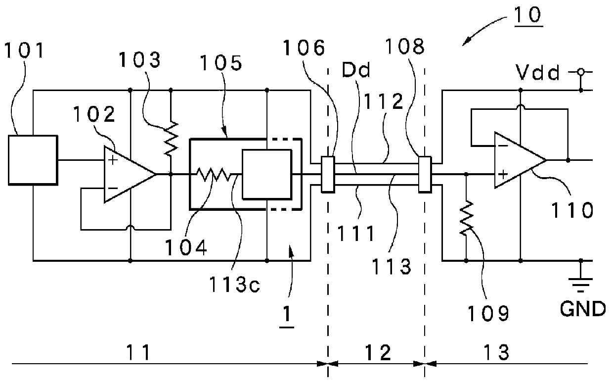
[0044] First, refer to figure 1 The overall configuration of the pressure detection device 10 including the disconnection detection circuit 1 of the present embodiment will be described.

[0045] The pressure detection device 10 is roughly divided into a pressure detection unit 11 , a control board 13 , and a wiring cable 12 connecting the pressure detection unit 11 and the control board 13 . The pressure detection unit 11 has a pressure detection unit 101 and an output amplifier 102 , and also has a pull-up resistor 103 and a voltage clamp circuit 105 constituting the disconnection detection circuit 1 . Also, the distribution cable 12 includes a power supply line 112, a GND line 111, and a signal line 113 for transmitting output signals. In addition, 106 and 108 denote sockets for wiring cables. In addition, the control board 13 has an input amplifier 110 and has...


PUM


Abstract

A disconnection detection circuit (1) includes: a pull-up resistor (103) to which the detection signal (Dd) is fed and which connects a signal line (113c) connected to the wiring cable (12) to a power supply (power supply voltage) (Vdd) or a pull-down resistor which connects the signal line (113c) to a GND; and a voltage clip circuit 105 (105a...) which includes a high-voltage clip circuit (105au...) which is connected between the signal line (113c) and the power supply (Vdd) and which clips the voltage of the signal line (113c) to the maximum specified voltage (Vdm) and a low-voltage clip circuit (105ad...) which is connected between the signal line (113c) and the GND and which clips the voltage of the signal line (113c) to the minimum specified voltage (Vds).

Description

technical field [0001] The present invention relates to a disconnection detection circuit suitable for a pressure detection device used for detecting pressure such as combustion pressure of an engine. Background technique [0002] A generally known pressure detection device is installed in an engine mounted on an automobile, and uses a built-in piezoelectric element (sensor element) to detect the pressure (combustion pressure) in the combustion chamber, usually as Figure 6 The configuration shown is installed on the engine. exist Figure 6 Among them, 601 denotes an automobile engine, 602 denotes a pressure detection unit, 603 denotes a wiring cable, and 604 denotes a control board. In this case, the pressure detection unit 602 is connected to the control board 604 via a wiring cable 603 including a power line, a GND line, and a signal line for transmitting a detection signal. The control board 604 has a function of controlling the engine 601 based on a detection signal fr...

Claims


Application Information

Patent Timeline
Patent Type & Authority Patents(China)
IPC IPC(8): G08C25/00G01L19/12G01L9/00G01R31/02
CPCG01L19/12G01L23/225G01L19/083
Inventor 中村里克四方山正德乡场哲也金森裕太
Owner CITIZEN FINEDEVICE
Why Eureka
Try Eureka