
Multifunctional projector structure
A projector and multi-functional technology, applied in the field of projectors, can solve the problems of poor stability, affecting the movement of indoor personnel, complex structure, etc.
- Summary
- Abstract
- Description
- Claims
- Application Information
AI Technical Summary
Problems solved by technology
Method used
Image

Examples
Embodiment Construction
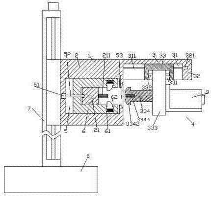
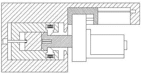
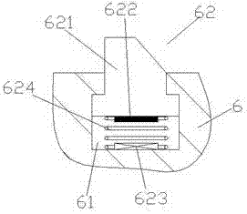
[0018] Such as Figure 1-Figure 8 As shown, a multi-functional projector structure of the present invention includes a joint connecting body 1 composed of a joint part 2 and a driving joint part 3 and an up-and-down adjustment device 7 arranged on the left side of the joint connecting body 1. The inside of the joint part 2 is provided with a locking cavity 5, and the center of the locking cavity 5 is provided with a fastening block 21 whose front end and rear end are respectively fixedly connected with the joint part 2, and the right side of the fastening block 21 is The end face is provided with an electric pole 211, and the outer side of the fastening block 21 is slidably connected with a locking and sliding part 6, and the locking and sliding part 6 is provided with a first threaded rod 52 that is connected with a helical thread. The bar 52 is extended to both sides, and the two sets of pillars on the right side of the lock and slide part 6 are symmetrically provided with a...
PUM
 Abstract
Description
Claims
Application Information