Transfer device for cam shaft

A transfer device and camshaft technology, which is applied in metal processing and other directions, can solve the problems of low efficiency, time-consuming and laborious, etc., and achieve the effect of simple device structure, smooth transfer, and fast and efficient transfer of camshafts

Inactive Publication Date: 2017-06-23
HUBEI XINYEGANG STEEL AUTO PARTS
View PDF0 Cites 0 Cited by
  • Summary
  • Abstract
  • Description
  • Claims
  • Application Information

AI Technical Summary

Problems solved by technology

[0002] In the camshaft processing workshop, in order to improve production efficiency and save labor costs, modern production often uses CNC machine tools for processing, and the large-scale processing of camshafts often uses multiple CNC machine tools for different processing procedures. When a process enters another process, in the actual production workshop, it is often transferred manually using specific tools, which is time-consuming, laborious, and inefficient

Method used


Image

  • Transfer device for cam shaft

Examples


Embodiment Construction

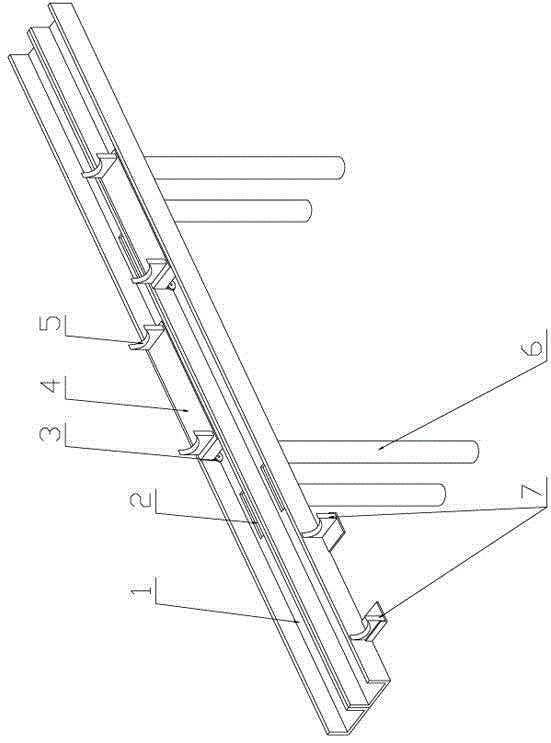
[0011] see figure 1 , the present invention is a camshaft transfer device, which has a leg 6, two guide rail grooves 1 with a rectangular cross section are arranged side by side on the leg, and 1-2 rolling camshaft rests are arranged in each guide rail groove The rolling camshaft shelf includes a bottom plate 4, two arc-shaped shelves 5 are arranged symmetrically on the left and right on the top of the bottom plate, and rolling wheels 3 are arranged on the bottom of the bottom plate. Match the settings.

[0012] In this embodiment, the groove bottom of each guide rail groove is provided with several dust removal ports 2, and the diameter of the dust removal ports is smaller than the installation width of the rolling wheels.

[0013] In this embodiment, several fixed camshaft shelves 7 are arranged on the outer wall of the guide rail groove.

[0014] When the device of the present invention is used, it is placed between two numerical control machine tools, and the worker only...


PUM


Abstract

The invention is a camshaft transfer device, which has supporting legs, and two guide rail grooves with rectangular cross section are arranged side by side on the supporting legs, and each guide rail groove is provided with 1-2 rolling camshaft shelves. The rolling camshaft shelf includes a bottom plate, two arc-shaped shelves are arranged symmetrically on the left and right on the top of the bottom plate, and rolling wheels are arranged on the bottom of the bottom plate, and the width of the bottom plate is set in cooperation with the guide rail groove; the device of the present invention The structure is simple, convenient and practical, and the transfer of the camshaft is fast and efficient during the production and processing of the camshaft, which has good promotion and application value, and is mainly used in the transfer of shaft products produced in the workshop.

Description

technical field [0001] The invention relates to the technical field of camshaft numerical control machining auxiliary tool equipment, in particular to a camshaft transfer device. Background technique [0002] In the camshaft processing workshop, in order to improve production efficiency and save labor costs, modern production often uses CNC machine tools for processing, and the large-scale processing of camshafts often uses multiple CNC machine tools for different processing procedures. When a process enters another process, in the actual production workshop, it is often transferred manually using specific tools, which is time-consuming, labor-intensive, and inefficient. Contents of the invention [0003] The object of the present invention is to provide a camshaft transfer device with simple structure and easy operation to solve the above-mentioned problems in mutual transfer of camshafts processed on different numerical control machine tools. [0004] The specific solut...

Claims


Application Information

Patent Timeline
Patent Type & Authority Applications(China)
IPC IPC(8): B23Q7/14
CPCB23Q7/1405
Inventor 张毓斌
Owner HUBEI XINYEGANG STEEL AUTO PARTS
Why Eureka
Try Eureka