Electric adjustable jack

An adjustable jack technology, applied in the direction of lifting devices, etc., can solve the problems of economic waste, limited jack lifting capacity, and the need to purchase additionally, and achieve the effect of reducing torque demand, reducing torque demand, and increasing lifting speed

Active Publication Date: 2017-11-10
JIANGSU UNIV OF SCI & TECH
View PDF4 Cites 4 Cited by
  • Summary
  • Abstract
  • Description
  • Claims
  • Application Information

AI Technical Summary

Problems solved by technology

This method has the following problems: since the upper lifting arm and the lower supporting arm of the traditional scissor jack are designed as a fixed straight rod shape, under the premise that the upper lifting arm and the lower supporting arm do not break, the lifting of the scissor jack The capacity depends on the torque that the motor on the jack can provide to the lead screw. In the application process of the scissor jack, when it is necessary to lift a large mass object, the motor is required to provide more torque to increase the jacking force, but due to The torque range that the motor can provide is fixed. At this time, the torque required by the jack often exceeds the maximum torque that the motor can provide. As a result, the motor on the jack cannot meet the lifting needs. For safety reasons, workers often It is necessary to purchase a new jack, which causes economic waste; when the jack is in a narrow working environment and needs to lift heavy objects from a low position, the jack requires the motor to output more torque to increase the load than the general situation. Big lift
Compared with the traditional jack, this structure has improved performance, but there are the following problems: After the lifting jib and the lower jib are limited by their respective rotation limit mechanisms, the lifting jib and the upper arm, the lower The angle between the support arm and the lower support jib is locked, and the entire lift assembly is fixed. When the torque required by the jack is still beyond the torque range that the motor can provide, it is impossible to adjust the upper arm and the upper lift jib. Between the angle between the lower support arm and the lower support auxiliary arm to continue to reduce the torque demand of the jack, thus limiting the further improvement of the lifting capacity of the jack; this invention only has one screw nut installed, and the motor mounting plate Friction is generated between the lead screw and the motor is required to output more torque to overcome the friction

Method used


Image

  • Electric adjustable jack
  • Electric adjustable jack
  • Electric adjustable jack

Examples


Embodiment Construction

[0030] The making and using of the embodiments are discussed in detail below. It should be understood, however, that the specific embodiments discussed are merely illustrative of specific ways to make and use the invention, and do not limit the scope of the invention. The expression of the structural position of each component such as up, down, top, bottom, etc. in the description is not absolute, but relative. These directional expressions are appropriate when the various components are arranged as shown in the drawings, but when the positions of the various components in the drawings are changed, these directional expressions are also changed accordingly.

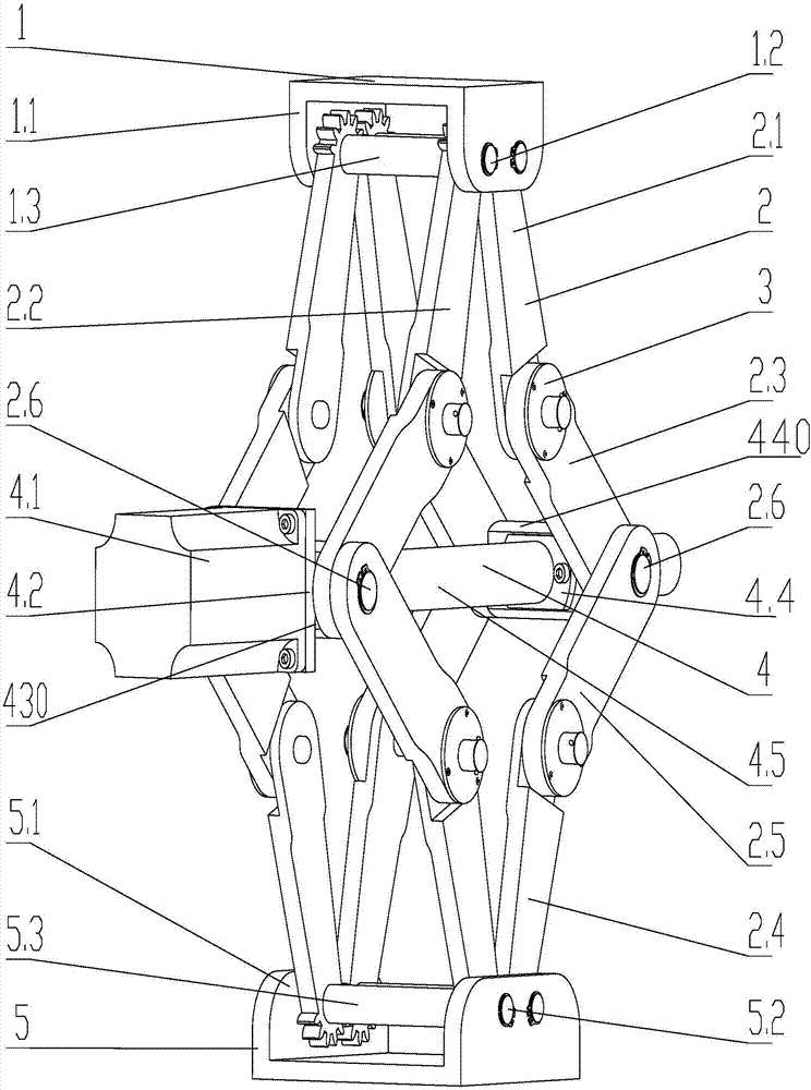
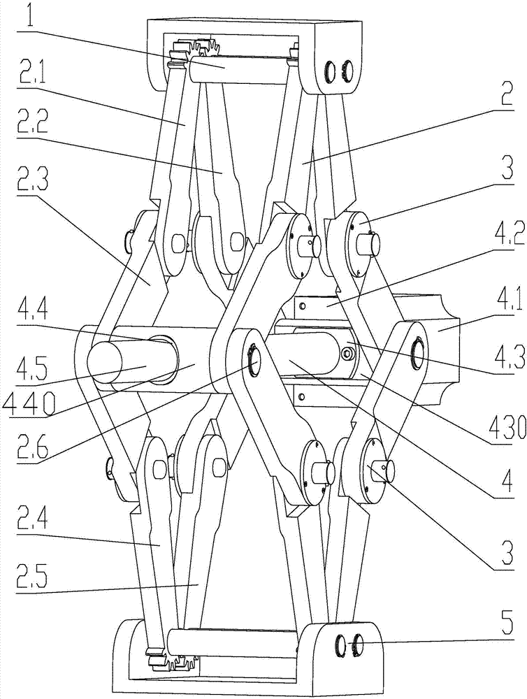
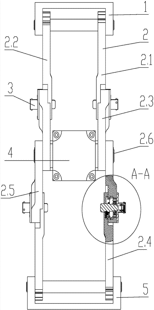
[0031] Such as Figure 1-2 As shown, an electric scissor jack with an adjustable bearing range has a structure comprising: a plug assembly 1 , a lifting assembly 2 , an automatic locking assembly 3 , a power transmission assembly 4 , and a base assembly 5 .

[0032] Such as figure 1 As shown, the plug assembly 1 mainly...


PUM


Abstract

The invention provides an electric adjustable jack which comprises a jack head assembly, a lifting assembly, a power transmission assembly and a base assembly. An automatic locking assembly is located in the lifting assembly. Compared with a straight rod shaped lifting assembly of a traditional scissor jack, when the lifting assembly with the bent state lifts an identical object to the same height, torque needing to be output by a motor is smaller, the lifting assembly can be adjusted to the ideal state according to the requirement of the application environment, the requirement of a jack for the torque output by the motor is lowered, and the lifting capacity of the jack can be improved temporarily, so that the jack adapts to the more narrow working environment, and meanwhile the jacking range of the jack is greatly enlarged.

Description

technical field [0001] The invention relates to an adjustable jack, which belongs to the field of lifting devices. Background technique [0002] In the prior art, the lifting device widely used in lifting and adjusting equipment is an electric scissor jack. The traditional electric scissor jack is generally composed of a jack, a pair of upper lifting arms, a pair of lower supporting arms, a base and a power transmission component, wherein the power transmission component mainly includes a motor, a motor mounting plate and a lead screw, while the upper lifting arm and the lower The supporting arms are all designed as straight rods; a pair of upper lifting arms and a pair of lower supporting arms are connected by front and rear pin shafts, the joints of the upper lifting arms are installed with head components, and the joints of the lower supporting arms are installed with bases. The leading screw passes through the front and rear pin shafts, and the front pin shaft at the cr...

Claims


Application Information

Patent Timeline
Patent Type & Authority Applications(China)
IPC IPC(8): B66F3/44B66F3/12
CPCB66F3/12B66F3/44
Inventor 刘吉涛苏世杰唐文献付灵懿王超
Owner JIANGSU UNIV OF SCI & TECH
Why Eureka
Try Eureka