Radiology department adjustable image viewing device

An adjustable and viewing technology, applied in optical elements, optics, instruments, etc., can solve the problem of inconvenient adjustment of viewing angles, and achieve the effect of easy viewing and preventing scratches

Inactive Publication Date: 2017-11-24
史志成
View PDF6 Cites 16 Cited by
  • Summary
  • Abstract
  • Description
  • Claims
  • Application Information

AI Technical Summary

Problems solved by technology

[0005] The present invention overcomes the physical examination such as filming in the hospital when general patients feel unwell. These X-ray films need to be carefully observed by doctors. However, many film viewing devices can only be viewed by doctors at present, and It is inconvenient to adjust the viewing angle, and some doctors need the assistance of foreign objects to better observe the shortcomings of X-ray films. The technical problem to be solved by the present invention is to provide an adjustable viewing device for radiology

Method used


Image

  • Radiology department adjustable image viewing device
  • Radiology department adjustable image viewing device
  • Radiology department adjustable image viewing device

Examples


Embodiment 1

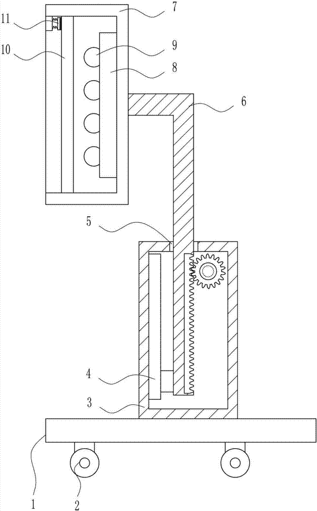
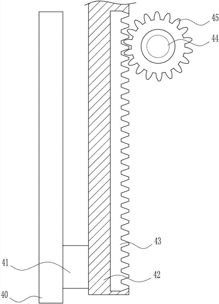
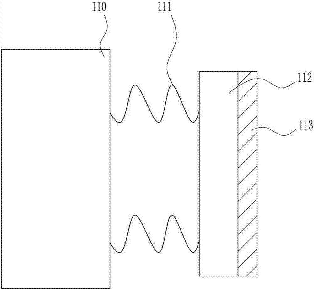
[0039] An adjustable film viewing device in the imaging department, such as Figure 1-7 As shown, it includes a base 1, wheels 2, a housing 3, a lifting mechanism 4, a pole 6, an observation frame 7, a lamp holder 8, a light bulb 9, a light-transmitting whiteboard 10, and a fixing mechanism 11. The bottom of the base 1 is provided with wheels 2 , the top of the base 1 is provided with a housing 3, the housing 3 is provided with a lifting mechanism 4, the housing 3 is provided with a pole 6, the pole 6 is connected with the lifting mechanism 4, and the top of the housing 3 is provided with a first guide hole 5 , the pole 6 passes through the first guide hole 5, the left end of the top of the pole 6 is provided with an observation frame 7, the right wall of the observation frame 7 is provided with a lamp holder 8, and a light bulb 9 is installed on the lamp holder 8, the top and the inside of the observation frame 7 A light-transmitting whiteboard 10 is arranged between the bott...

Embodiment 2

[0041] An adjustable film viewing device in the imaging department, such as Figure 1-7 As shown, it includes a base 1, wheels 2, a housing 3, a lifting mechanism 4, a pole 6, an observation frame 7, a lamp holder 8, a light bulb 9, a light-transmitting whiteboard 10, and a fixing mechanism 11. The bottom of the base 1 is provided with wheels 2 , the top of the base 1 is provided with a housing 3, the housing 3 is provided with a lifting mechanism 4, the housing 3 is provided with a pole 6, the pole 6 is connected with the lifting mechanism 4, and the top of the housing 3 is provided with a first guide hole 5 , the pole 6 passes through the first guide hole 5, the left end of the top of the pole 6 is provided with an observation frame 7, the right wall of the observation frame 7 is provided with a lamp holder 8, and a light bulb 9 is installed on the lamp holder 8, the top and the inside of the observation frame 7 A light-transmitting whiteboard 10 is arranged between the bott...

Embodiment 3

[0044] An adjustable film viewing device in the imaging department, such as Figure 1-7 As shown, it includes a base 1, wheels 2, a housing 3, a lifting mechanism 4, a pole 6, an observation frame 7, a lamp holder 8, a light bulb 9, a light-transmitting whiteboard 10, and a fixing mechanism 11. The bottom of the base 1 is provided with wheels 2 , the top of the base 1 is provided with a housing 3, the housing 3 is provided with a lifting mechanism 4, the housing 3 is provided with a pole 6, the pole 6 is connected with the lifting mechanism 4, and the top of the housing 3 is provided with a first guide hole 5 , the pole 6 passes through the first guide hole 5, the left end of the top of the pole 6 is provided with an observation frame 7, the right wall of the observation frame 7 is provided with a lamp holder 8, and a light bulb 9 is installed on the lamp holder 8, the top and the inside of the observation frame 7 A light-transmitting whiteboard 10 is arranged between the bott...


PUM


Abstract

The invention relates to an image viewing device, and especially relates to a radiology department adjustable image viewing device. The technical problem to be solved by the invention is to provide a radiology department adjustable image viewing device. The radiology department adjustable image viewing device includes a pedestal, wheels, a housing, an elevating mechanism, a pole, an observation frame, a lamp socket, bulbs and the like, wherein the wheels are arranged at the bottom of the pedestal; the housing is arranged at the top of the pedestal; the elevating mechanism is arranged in the housing; the pole is arranged in the housing; the pole is connected with the elevating mechanism; a first guide hole is formed in the top of the housing; the pole penetrates through the first guide hole; the observation frame is arranged at the left end of the top of the pole; the lamp socket is arranged at the right wall in the observation frame; and the bulbs are arranged on the lamp socket. The radiology department adjustable image viewing device achieve the effect of adjusting the angle and preferably assisting doctors, and has the advantages of being simple in operation, being convenient to use, and being high in promotional performance.

Description

technical field [0001] The invention relates to a film viewing device, in particular to an adjustable film viewing device for imaging department. Background technique [0002] Medical imaging refers to the technology and processing process of obtaining internal tissue images of the human body or a certain part of the human body in a non-invasive manner for medical treatment or medical research. It includes the following two relatively independent research directions: medical imaging system and medical image processing. The former refers to the process of image formation, including the research on imaging mechanism, imaging equipment, imaging system analysis and other issues; the latter refers to the further processing of the obtained image, the purpose of which is to make the original image that is not clear enough Restoration, or to highlight certain feature information in the image, or to classify the image as a pattern, etc. [0003] Generally, when patients are unwell,...

Claims


Application Information

Patent Timeline
Patent Type & Authority Applications(China)
IPC IPC(8): G02B27/02
CPCG02B27/028
Inventor 史志成李丽梅伦子茵
Owner 史志成
Why Eureka
Try Eureka