Support structure for floor casting

A supporting structure and floor slab technology, which is applied in building construction, on-site preparation of building components, construction, etc., can solve the problem that the force direction of the steel wire on the honeycomb core is not easy to control, the honeycomb core is prone to displacement, and the positioning accuracy of the honeycomb core is low and other issues to achieve the effect of high availability

Inactive Publication Date: 2017-12-29
李忠华
View PDF1 Cites 0 Cited by
  • Summary
  • Abstract
  • Description
  • Claims
  • Application Information

AI Technical Summary

Problems solved by technology

[0004] In view of the above-mentioned prior art, the force direction of the steel wire on the honeycomb core is not easy to control, especially in the process of concrete pouring, the honeycomb core is prone to displacement, so the above constraint scheme for the honeycomb core has low

Method used


Image

  • Support structure for floor casting

Examples


Embodiment 1

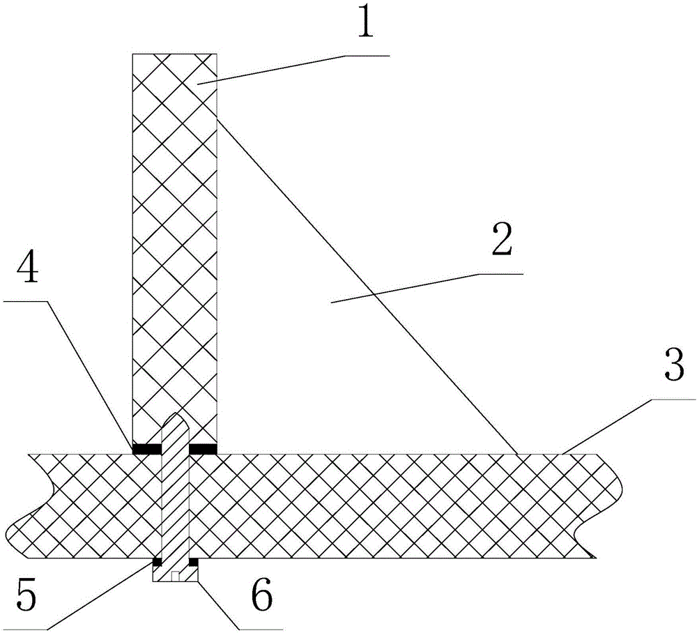
[0021] Such as figure 1 As shown, a support structure for floor slab pouring includes a bottom formwork 3, and also includes a side panel 1 and a connecting screw 6, and the side panel 1 is installed on the upper surface of the bottom formwork 3 through the connection screw 6, and the The connecting screw 6 passes through the bottom template 3 from the bottom surface of the bottom template 3 and is threadedly connected with the side panel 1 .

[0022] Specifically, this structure is used to pour the floor slabs with built-in honeycomb cores, that is, after the bottom formwork 3 and steel beams are erected, the honeycomb cores are placed on the bottom formwork 3, and the concrete is poured after the position constraints of the honeycomb cores are completed. A floor slab with a built-in honeycomb core is obtained.

[0023] In this solution, the upper side panel 1 is used to interact with the side of the honeycomb core to limit the position of the honeycomb core. In this way, it...

Embodiment 2

[0025] Such as figure 1 As shown, this embodiment is further limited on the basis of Embodiment 1: a first sealing strip 4 is sandwiched between the bottom template 3 and the side panel 1, and the side panel 1 forms a complete Rectangle. In the prior art, in order to avoid grout leakage in the gap between the honeycomb core and the bottom formwork 3, it is generally necessary to install a sealing ring between the honeycomb core and the bottom formwork 3, and the above sealing ring is used when adjusting the position of the honeycomb core and pouring concrete. There may also be a certain displacement relative to the honeycomb core. At the same time, since the sealing ring cannot be guaranteed to receive sufficient sealing specific pressure during subsequent concrete pouring, the actual sealing reliability of the above sealing rings is not high during use. In this solution, by setting the entire surface of the side of the honeycomb core or the bottom side of the side to fit the...

Embodiment 3

[0031] Such as figure 1 As shown, this embodiment further limits this case on the basis of the technical solution provided in Example 1, as the specific implementation of the bottom formwork 3 and the side panel 1, the bottom formwork 3 and the side panel 1 are both wooden boards . That is, the scheme can be well realized by adopting the widely used wooden formwork in the prior art.


PUM


Abstract

The invention discloses a support structure for floor slab pouring, which comprises a bottom formwork, and also includes side panels and connecting screws. The side panels are installed on the upper surface of the bottom formwork through The bottom surface of the formwork passes through the bottom formwork and is threadedly connected with the side panel. The supporting structure has low implementation cost, and can effectively control the positioning accuracy of the honeycomb core in space.

Description

technical field [0001] The invention relates to the technical field of building construction, in particular to a support structure for floor pouring. Background technique [0002] Among the existing building forms, the honeycomb core floor has the following advantages: first, it is convenient for construction, and the mandrel can be placed directly, reducing the amount of concrete, shortening the maintenance time, and can also speed up the construction progress and shorten the construction period; second, it has good bearing performance , suitable for large spans; the third is that when the same bearing capacity is achieved, less concrete and other materials are used, so its own weight is also small, the economy is better, the plate thickness is thinner than other structures, and the net height of the floor can be increased; the fourth is relative Compared with other rib beam structures, the bottom plate makes the honeycomb core floor flat and beautiful; fifth, it has good s...

Claims


Application Information

Patent Timeline
IPC IPC(8): E04G11/36E04G17/00
CPCE04G11/36E04G11/365E04G17/001
Inventor 李忠华
Owner 李忠华
Why Eureka
Try Eureka