Display panel and display device

A display panel and display device technology, which is applied to static indicators, instruments, semiconductor devices, etc., and can solve the problems of poor display uniformity and unsatisfactory display effects of special-shaped display panels

Active Publication Date: 2018-01-19
WUHAN TIANMA MICRO ELECTRONICS CO LTD
View PDF7 Cites 101 Cited by
  • Summary
  • Abstract
  • Description
  • Claims
  • Application Information

AI Technical Summary

Problems solved by technology

In this case, the pixels of the special-shaped part of the display area can no longer be arranged in a rectangular array, so the number of pixels in each row is not necessarily the same, so the loads of the scanning lines driving different rows of pixels are no longer the same, which leads to the difference between the special-shaped area and When the scanning lines in the non-special-shaped area provide the same scanning signal, the display brightness of the special-shaped area and the non-special-shaped area are also inconsistent. Therefore, the display uniformity of the special-shaped display panel is poor, and the display effect is not ideal.

Method used


Image

  • Display panel and display device
  • Display panel and display device
  • Display panel and display device

Examples


Embodiment Construction

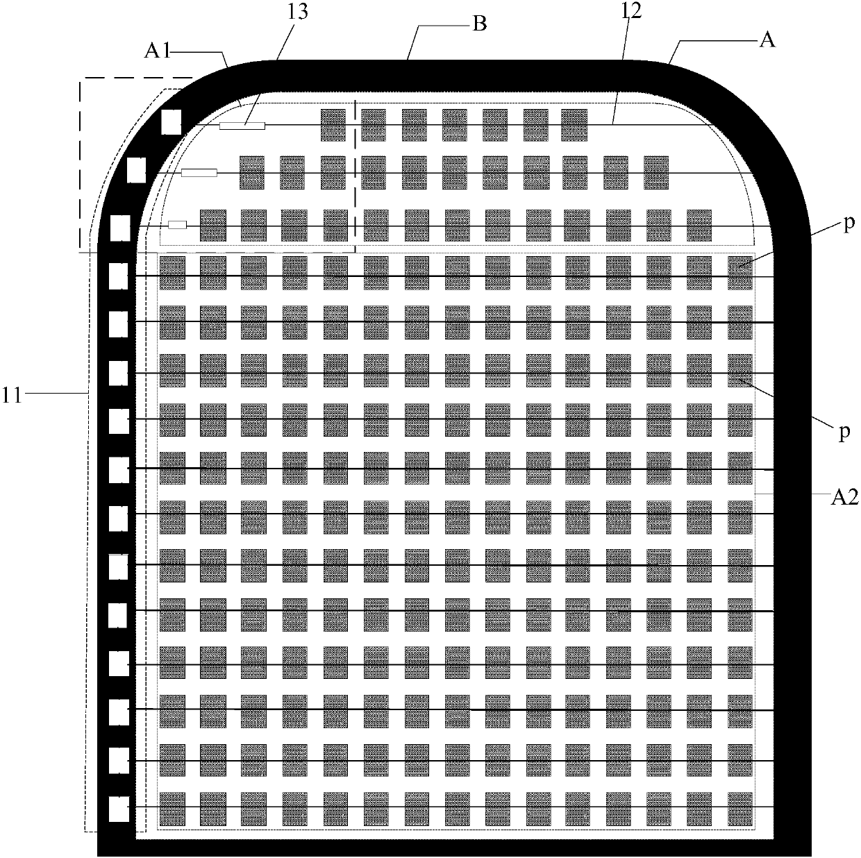
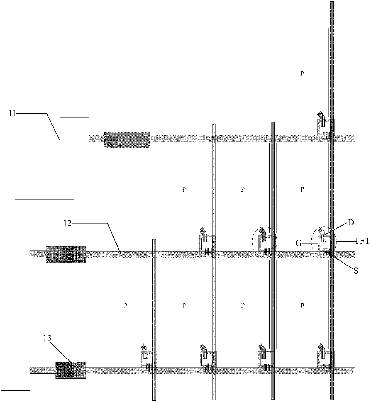
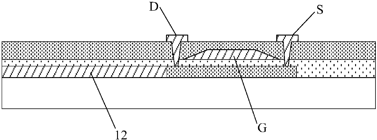
[0058] Embodiments of the present invention provide a display panel and a display device, which are used to improve uniformity of display brightness and optimize display effect.

[0059] In order to make the above objects, features and advantages of the present invention more comprehensible, the present invention will be further described below in conjunction with the accompanying drawings and embodiments. Example embodiments may, however, be embodied in many forms and should not be construed as limited to the embodiments set forth herein; rather, these embodiments are provided so that this disclosure will be thorough and complete, and will fully convey the concept of example embodiments to those skilled in the art. The same reference numerals denote the same or similar structures in the drawings, and thus their repeated descriptions will be omitted. The words expressing position and direction described in the present invention are all described by taking the accompanying dra...


PUM


Abstract

The invention discloses a display panel and a display device. A display area comprises a first display region and a second display region. Each of the first display region and the second display region comprises a plurality of pixels in array distribution. The number of at least one line of pixels of the first display region is smaller than the number of any line of pixels of the second display region. The display panel comprises a grid drive circuit, a plurality of scanning signal lines and resistance compensation units. At least one scanning signal line provides scanning signals to one lineof the pixels. The resistance compensation units, namely metal or metal oxide wires, are connected with the scanning signal lines of the first display region. Through connection between the scanning signal lines of the first display region and the resistance compensation units, load of the scanning signal lines connected with the resistance compensation units can be increased, so that load differences among the scanning signal lines of the first display region and load differences among the scanning signal lines of the second display region are reduced, display uniformity of the display panelis improved, and display effect is enhanced.

Description

technical field [0001] The invention relates to the field of display technology, in particular to a display panel and a display device. Background technique [0002] Display panels commonly used at the present stage can generally be divided into a display area for image display and a non-display area for setting peripheral driving circuits and the like. The pixels distributed in an array in the display area are respectively connected to the driving circuit in the non-display area through a switch element. Usually, each switching element is connected to a scanning line and a data line, the switching element is turned on by receiving the scanning signal of the scanning line, and the pixel is driven to display a certain gray scale by receiving the data signal of the data line. The switching elements are connected to scan lines and data lines in different combinations, so that each pixel can emit light independently. Currently, the display areas of common display panels are al...

Claims


Application Information

Patent Timeline
Patent Type & Authority Applications(China)
IPC IPC(8): G09G3/20
CPCG09G2310/0232G09G3/3266G09G2320/0233G09G3/3225H01L27/124H10K59/1315H10K59/131H10K59/00
Inventor 杨星星
Owner WUHAN TIANMA MICRO ELECTRONICS CO LTD
Why Eureka
Try Eureka