Pull head mounting machine

A head machine and slider technology, applied in the direction of sliding fastener components, applications, fasteners, etc., can solve the problems of high labor cost and low labor efficiency, and achieve the effects of simple structure, stable operation and stable working state.

Pending Publication Date: 2018-02-23
温州宏业精机有限公司
View PDF11 Cites 2 Cited by
  • Summary
  • Abstract
  • Description
  • Claims
  • Application Information

AI Technical Summary

Problems solved by technology

Due to the small size of the zipper, it requires more attention and energy to operate, so the manual operation is not efficient and the labor cost is expensive

Method used


Image

  • Pull head mounting machine
  • Pull head mounting machine
  • Pull head mounting machine

Examples


Embodiment Construction

[0037] The present invention will be further described below in conjunction with accompanying drawing with specific embodiment:

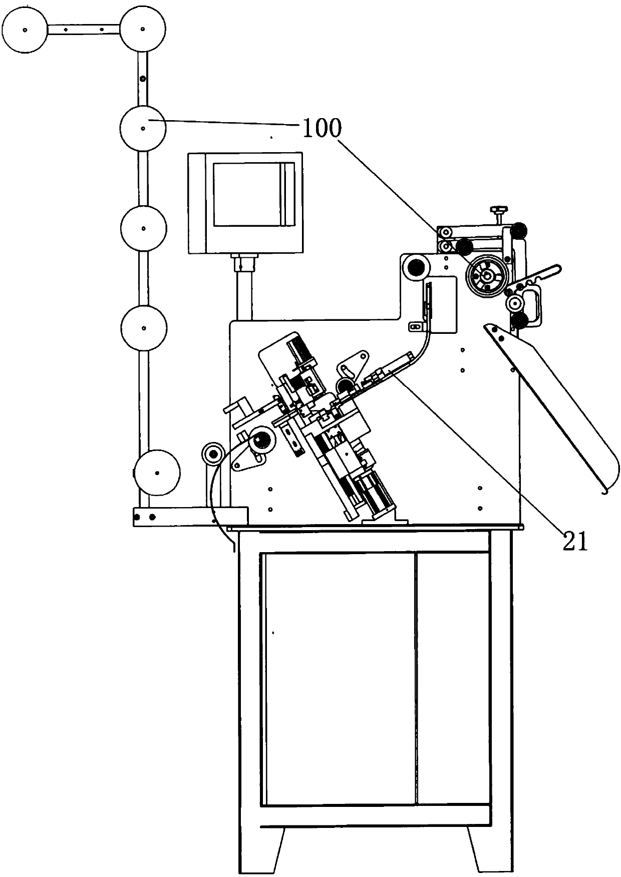
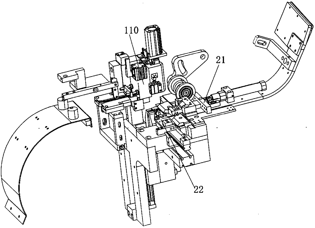
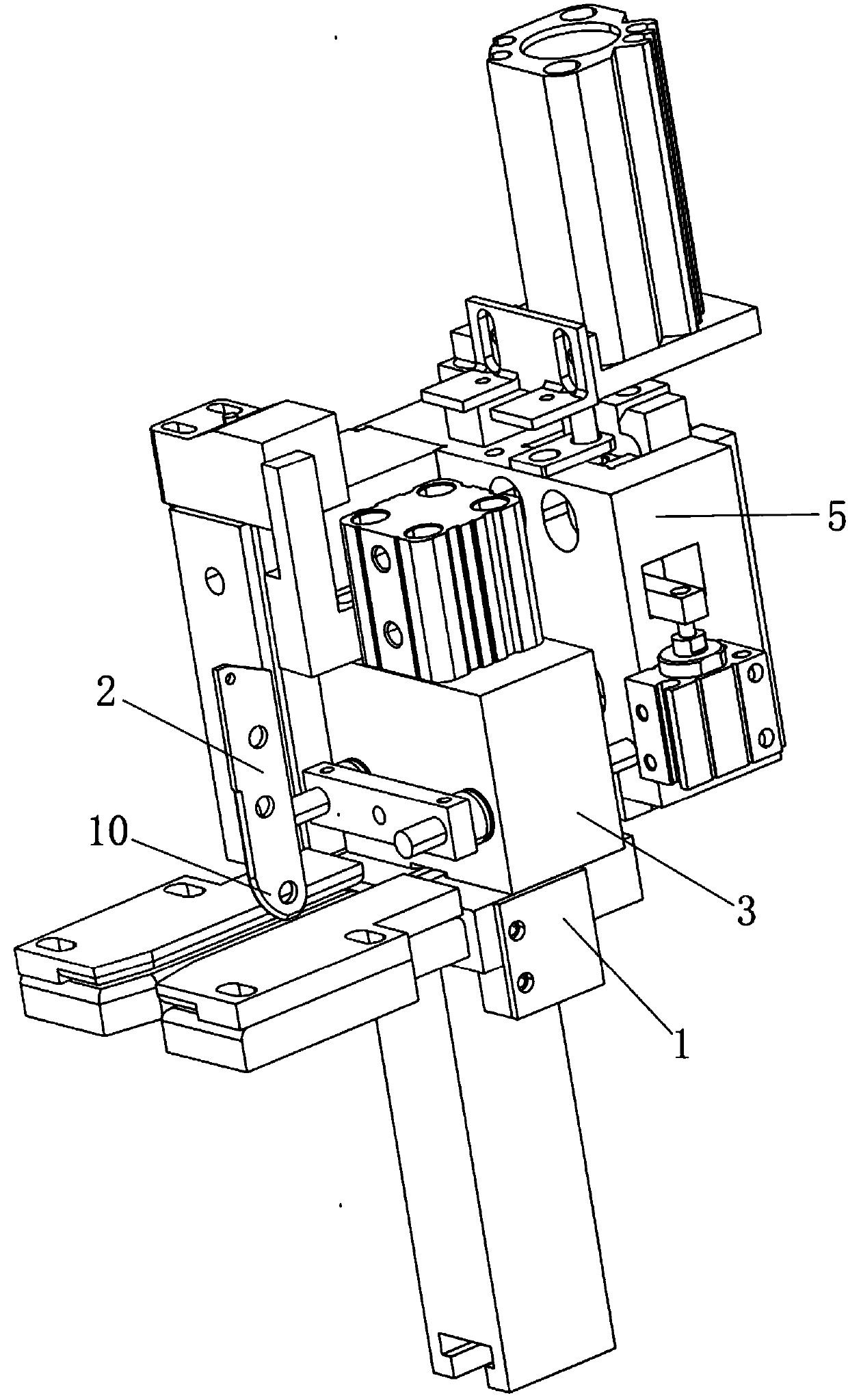
[0038]A slider-up machine, comprising a zipper conveying device 100, a slider conveying device, a chain splitting device 110 and a chain combining device, the chain splitting device including a chain splitting platform 1 and a first driving device that drives the chain splitting unit 1 to move up and down , the front of the chain dividing platform 1 is provided with an induction part 2, and the upper surface of the dividing chain platform 1 is provided with a slider 3 that can move along the direction of zipper conveying, and the slider 3 is provided with a first minute hand 4 and for the first minute hand to move up and down. In the telescopic space of the movement, the slider 3 is fixed with a second driving device that drives the first minute hand 4 to move up and down, and a fixing frame 5 is arranged behind the chain dividing table 1, and a seco...


PUM


Abstract

The invention belongs to the field of zipper equipment and in particular relates to a novel pull head mounting machine. The pull head mounting machine comprises a zipper stripping device, wherein thezipper stripping device comprises a zipper stripping platform, a sensing piece is arranged in front of the zipper stripping platform, a sliding block which can move along a zipper conveying directionis arranged on the upper surface of the zipper stripping platform, a first stripping needle is arranged in the sliding block, a fixation frame is arranged at the rear of the zipper stripping platform,a second stripping needle is arranged in the fixation frame, a pull head conveying device comprises a pull head mould, a pull head fixation position is moulded on the pull head mould, the pull head mould rises to a set position, and the pull head fixation position is located between the zipper stripping platform and the second stripping needle; and a stop block is arranged on the zipper strippingplatform, a first reset spring is arranged between the bottom of the stop block and the bottom of a stop slot, space between the stop block and the fixation frame is equal to width of the sliding block, and a first reset device used for driving the sliding block to be far away from the fixation frame is arranged on the sliding block. The pull head mounting machine has the advantages of simple structure, convenience in use, high pull head mounting efficiency, conservation of labor cost and high degree of automation.

Description

technical field [0001] The invention belongs to the field of zipper equipment, in particular to a novel pull-up machine. Background technique [0002] The traditional zipper pull-up process includes dividing the chain belt into the slider, pressing the chain belt against the slider, and then the zipper walks a certain distance to complete the entire slider-up process, and the entire slider-up process is It is done manually. Due to the small size of the zipper, it requires higher attention and energy to operate, so the manual operation is not efficient and the labor cost is expensive. Contents of the invention [0003] The purpose of the present invention is to provide a new type of pulling head machine with simple structure, convenient use, high pulling head efficiency, labor cost saving and high degree of automation. [0004] The purpose of the present invention is achieved like this: [0005] A slider machine, comprising a zipper conveying device, a slider conveying d...

Claims


Application Information

Patent Timeline
Patent Type & Authority Applications(China)
IPC IPC(8): A44B19/62
CPCA44B19/62
Inventor 张岳恩
Owner 温州宏业精机有限公司
Why Eureka
Try Eureka