Display panel with camera function and electronic device

A display panel and functional technology, applied in the direction of instruments, nonlinear optics, optics, etc., can solve the problems of inconvenient and manual flipping of products by users

Active Publication Date: 2020-10-23
JRD COMM (SHENZHEN) LTD
View PDF7 Cites 0 Cited by
  • Summary
  • Abstract
  • Description
  • Claims
  • Application Information

AI Technical Summary

Problems solved by technology

But this method requires the user to flip the product manually, which is inconvenient

Method used


Image

  • Display panel with camera function and electronic device
  • Display panel with camera function and electronic device
  • Display panel with camera function and electronic device

Examples


Embodiment 1

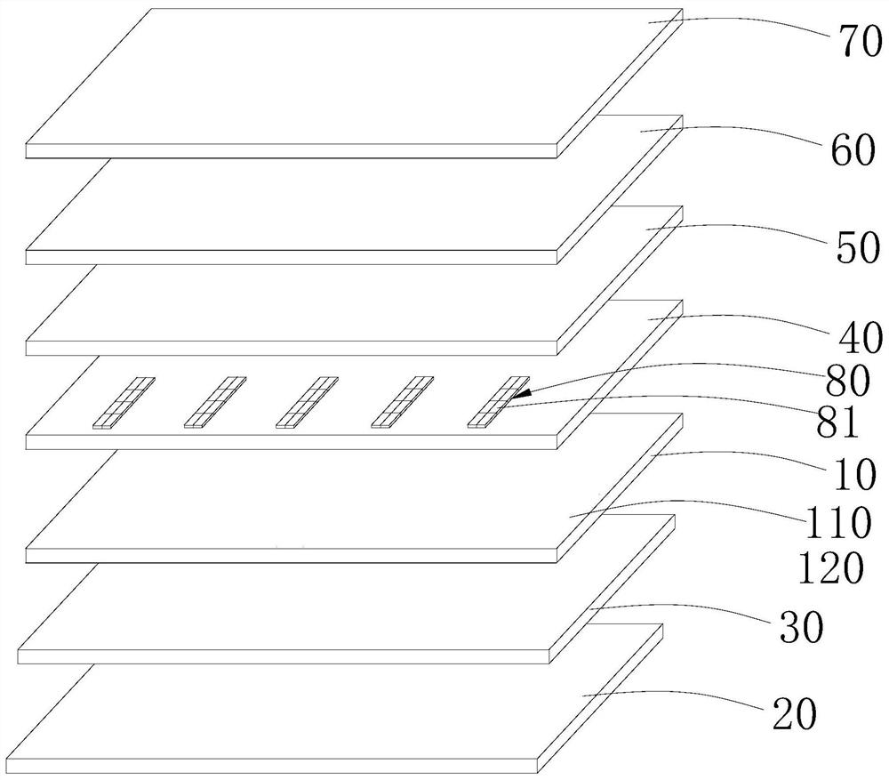
[0022] like figure 1 As shown, the display panel with camera function in this embodiment includes a backlight 20, a lower polarizer 30 located on the upper layer of the backlight 20, an array substrate 10 located on the upper layer of the lower polarizer 30, a liquid crystal layer 40 located on the upper layer of the array substrate 10, The upper substrate 50 located on the upper layer of the liquid crystal layer 40 , the color filter 60 located on the upper layer of the upper substrate 50 and the upper polarizer 70 located on the upper layer 60 of the color filter.

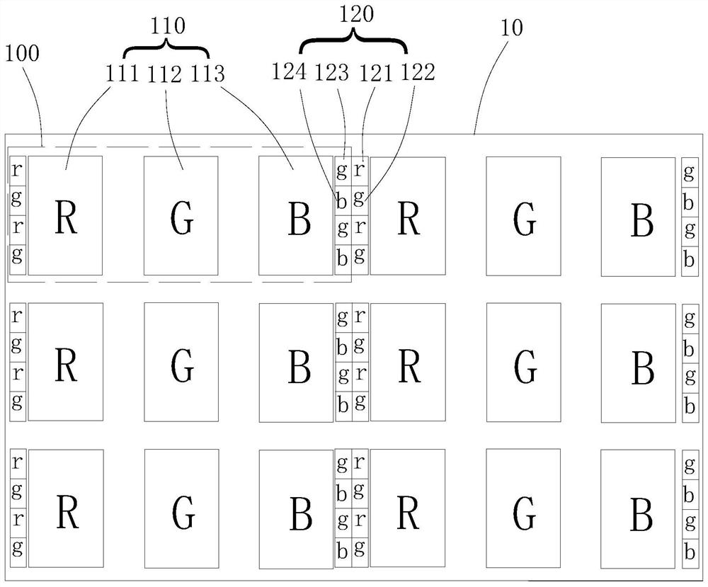
[0023] like figure 2 As shown, a plurality of pixel units 100 are arranged on the array substrate 10, and the pixel unit 100 includes a liquid crystal pixel unit 110 for image display and a photosensitive pixel unit 120 for responding to an optical signal, the liquid crystal pixel unit 110 and the photosensitive pixel unit 120 Located on the same layer, the display panel further includes a control circuit elect...

Embodiment 2

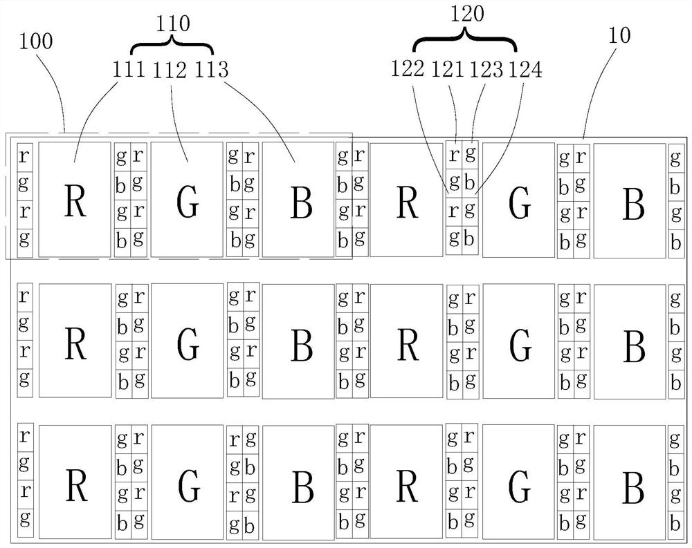
[0030] like image 3 As shown, the difference between the present embodiment and the first embodiment is that: there are multiple light-sensitive pixel units 120, and the first display pixel 111, the second display pixel 112, and the third display pixel 113 are arranged at intervals in sequence. The left side of a display pixel 111, the left side of the second display pixel 112, and the left side of the third display pixel 113 are all provided with a first pixel unit, and the right side of the first display pixel 111, the right side of the second display pixel 112, and the third display pixel The right side of 113 is provided with a second pixel unit. In this way, more photosensitive pixels are provided in one pixel unit 100, which can improve the photographing performance.

Embodiment 3

[0032] like Figure 4 As shown, the difference between the present embodiment and the first embodiment is that the number of each photosensitive pixel unit 120 is multiple, and the four sub-pixels of the photosensitive pixel unit 120 are arranged in two rows and two columns, and the liquid crystal pixel unit 110 Photosensitive pixel units 120 are provided on the left and right sides. That is, a row of second pixel units is provided outside the row of first pixel units on the left side of the liquid crystal pixel unit 110 , and a row of first pixel units is provided outside the row of second pixel units on the right side of the liquid crystal pixel unit 110 . As a preferred embodiment, each pixel unit 100 includes four light-sensitive pixel units 120, wherein two light-sensitive pixel units 120 are arranged in a row and are located on the left side of the liquid crystal pixel unit 110, and the other two light-sensitive pixel units 120 are arranged in a row. rows are located on...


PUM


Abstract

The invention discloses a display panel with an image capturing function. The display panel includes an array substrate and a plurality of pixel units disposed on the array substrate. Each of the pixel units includes a liquid crystal pixel unit and a photosensitive pixel unit, the liquid crystal pixel includes a first display pixel, a second display pixel, and a third display pixel in the same row, the photosensitive pixel unit includes a first pixel unit and a second pixel unit, the first pixel unit includes a first sub-pixel and a second sub-pixel, the second pixel unit includes a third sub-pixel and a fourth sub-pixel, each of the display pixels and each of the sub-pixels do not overlap, and adjacent two sub-pixels have different colors. The invention provides a display panel and electronic device with an image capturing function, wherein photosensitive pixels are added in the gaps of liquid crystal pixels to realize the image capturing function of the display panel and do not affect the image display of the display panel, and at the same time, the photosensitive pixels are advantageous for the electronic device to achieve a higher screen occupation ratio.

Description

technical field [0001] The invention relates to the field of liquid crystal display panels, and more specifically, to a display panel with camera function and electronic equipment. Background technique [0002] At present, the front camera of mobile terminal products has become a standard configuration. Most of the front cameras are used as additional components to occupy the space on the front of the screen, which cannot meet the user's experience requirements for the screen to only be used as a display function and reduce other non-display functions. Some mobile phone brands adopt the configuration of moving the camera to the lower corner, which makes the display area of ​​the upper part of the screen account for a larger proportion. However, this method requires the user to manually flip the product, which is inconvenient. Contents of the invention [0003] The technical problem to be solved by the present invention is to overcome the deficiencies of the prior art and ...

Claims


Application Information

Patent Timeline
Patent Type & Authority Patents(China)
IPC IPC(8): G02F1/1333
CPCG02F1/1333G02F1/13338G02F2201/52G02F2201/58
Inventor 于洋马记涛
Owner JRD COMM (SHENZHEN) LTD
Why Eureka
Try Eureka