Heat exchange device and air-conditioning equipment

A technology for heat exchange devices and heat exchangers, which is applied in the field of air conditioning equipment and heat exchange devices, and can solve the problems of restrained energy efficiency ratio, weakened heat transfer efficiency of refrigerant tubes or fins, and insufficient heat transfer efficiency of heat exchangers, etc. , to achieve the effect of improving energy efficiency ratio and ensuring heat exchange efficiency

Inactive Publication Date: 2018-05-08
GD MIDEA AIR-CONDITIONING EQUIP CO LTD +1
View PDF8 Cites 4 Cited by
  • Summary
  • Abstract
  • Description
  • Claims
  • Application Information

AI Technical Summary

Problems solved by technology

[0002] In existing air-conditioning equipment, finned heat exchangers are generally used, and the finned heat exchangers realize the cooling and heating operation of the equipment by exchanging heat with the air flow passing through them. In the process of realizing the present invention, the inventors It is found that there are at least the following problems in the prior art: the flow rate of air in the air conditioner is generally within a certain range. For conventional finned heat exchangers, when the air flows

Method used


Image

  • Heat exchange device and air-conditioning equipment
  • Heat exchange device and air-conditioning equipment
  • Heat exchange device and air-conditioning equipment

Examples


Embodiment Construction

[0040] In order to understand the above-mentioned purpose, features and advantages of the present invention more clearly, the present invention will be further described in detail below in conjunction with the accompanying drawings and specific embodiments. It should be noted that, in the case of no conflict, the embodiments of the present application and the features in the embodiments can be combined with each other.

[0041] In the following description, many specific details are set forth in order to fully understand the present invention. However, the present invention can also be implemented in other ways different from those described here. Therefore, the protection scope of the present invention is not limited by the specific details disclosed below. EXAMPLE LIMITATIONS.

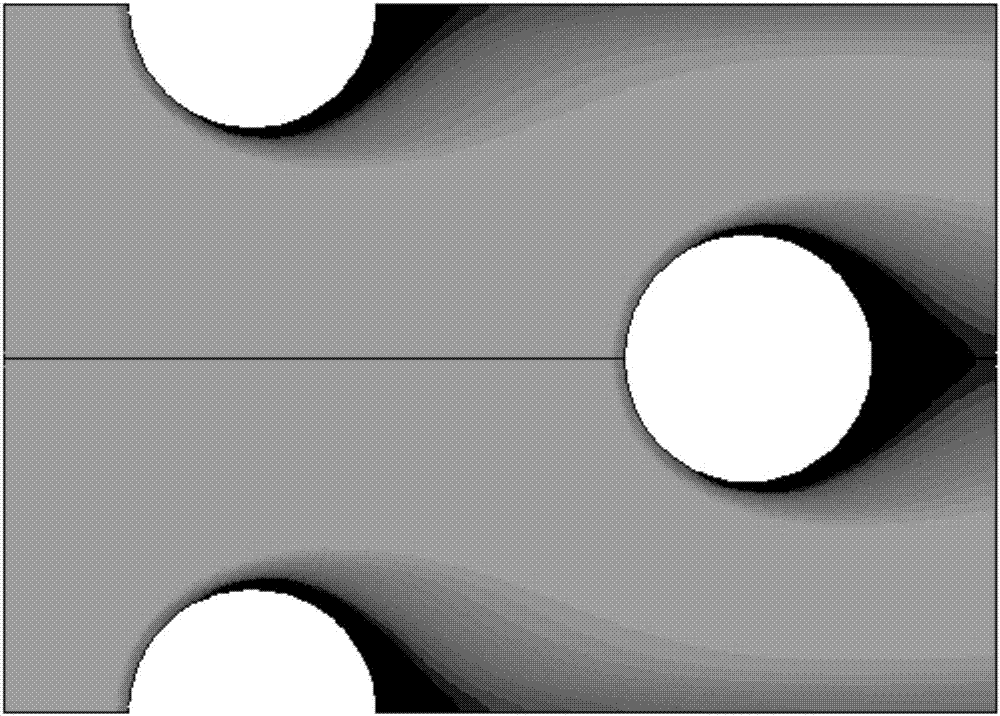
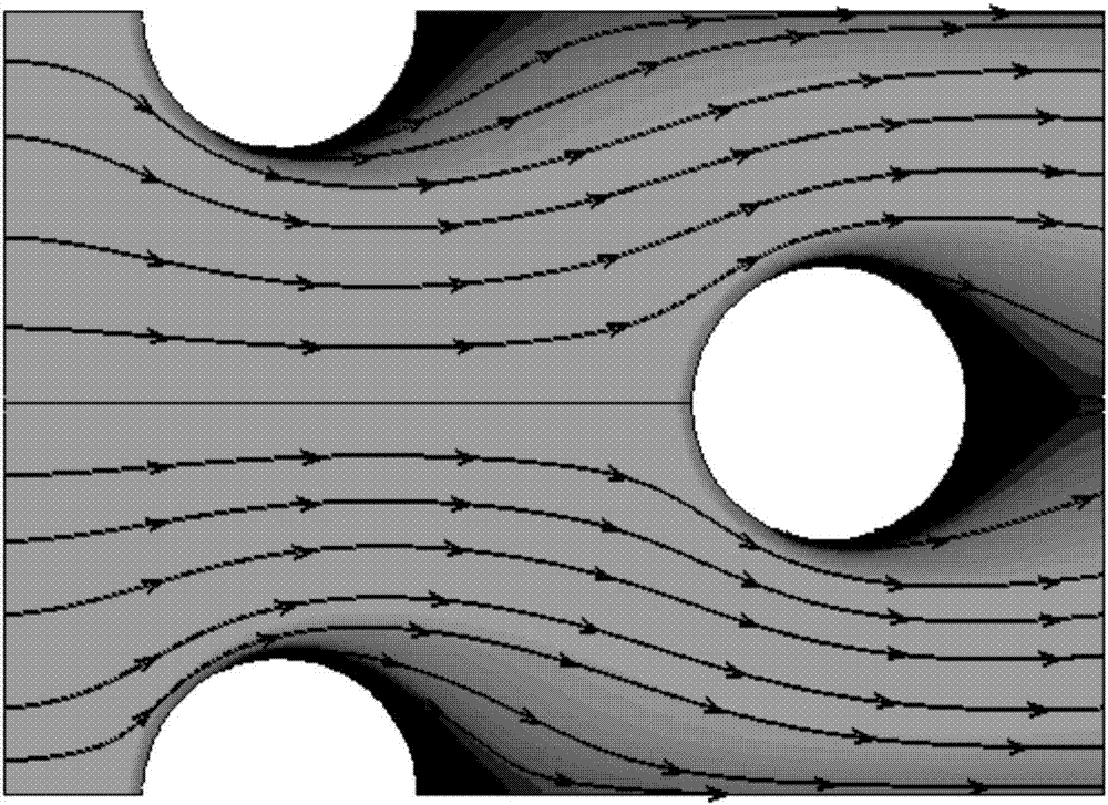
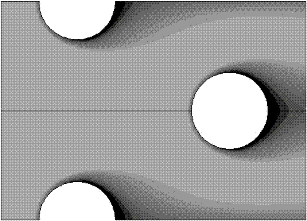
[0042] Refer below Figure 3 to Figure 8 The heat exchange device and air conditioning equipment according to some embodiments of the present invention are described.

[0043] Such as Figure 5 to...


PUM


Abstract

The invention provides a heat exchange device and air-conditioning equipment. The heat exchange device comprises at least two subsidiary heat exchangers arranged in the wind direction; each subsidiaryheat exchanger comprises at least one row of refrigerant pipes and fins mounted on the refrigerant pipes in a sleeving manner; and the transverse pipe center distance of the refrigerant pipes betweenany two adjacent subsidiary heat exchangers ranges from 8 mm to 35 mm. According to the heat exchange device provided in the scheme, an air flow can extend fully and smoothly when flowing among the refrigerant pipes of the adjacent subsidiary heat exchangers, air flow blind zones and weak wind zones on the leeward sides of the refrigerant pipes can be reduced, all the refrigerant pipes in the subsidiary heat exchangers in the upstream and downstream positions of the wind direction can make full contact with the air flow, the problem that the refrigerant pipes in the subsidiary heat exchangersin the downstream position of the wind direction cannot exchange heat effectively due to the fact that the refrigerant pipes are located in the air flow blind zones or the weak wind zones is avoided,the problem that the wind force on the subsidiary heat exchangers in the downstream position of the wind direction is greatly reduced due to the excessively large transverse pipe center distances ofthe refrigerant pipes between among any subsidiary heat exchangers can also be avoided with the design, and the overall energy efficiency ratio of the air-conditioning equipment is increased.

Description

technical field [0001] The present invention relates to the field of air conditioners, in particular to a heat exchange device and an air conditioner. Background technique [0002] In existing air-conditioning equipment, finned heat exchangers are generally used, and the finned heat exchangers realize the cooling and heating operation of the equipment by exchanging heat with the air flow passing through them. In the process of realizing the present invention, the inventors It is found that there are at least the following problems in the prior art: the flow rate of air in the air conditioner is generally within a certain range. For conventional finned heat exchangers, when the air flows through the refrigerant tubes of the finned heat exchanger, the refrigerant will The leeward side of the tube forms a certain airflow blind area or weak wind area, which causes the heat transfer efficiency of the refrigerant tube or fin located downstream in the wind direction and in the air ...

Claims


Application Information

Patent Timeline
IPC IPC(8): F24F13/30
CPCF24F13/30
Inventor 郑坚斌刘从峰何杜兵林军国
Owner GD MIDEA AIR-CONDITIONING EQUIP CO LTD
Why Eureka
Try Eureka