Distributed residual current measuring system

A residual current and measuring system technology, applied in the direction of measuring devices, measuring only current, measuring electrical variables, etc., can solve the problems of long time, manual operation only, no data correlation, etc. good safety effect

Pending Publication Date: 2018-05-18
SMART HLDG CO LTD
View PDF5 Cites 0 Cited by
  • Summary
  • Abstract
  • Description
  • Claims
  • Application Information

AI Technical Summary

Problems solved by technology

[0003] In the existing technology, the equipment for measuring the remaining power is independent, has no data association, and has no network data association, and the operation is only manual
The original single-phase residual current detector is used independently, without forming a network, and there is no network scheduling control algorithm to determine the fault loop inside the network. It is only for measurement and control of a single target. Knowing that the residual current of the current circuit exceeds the limit, it is impossible to accurately determine which circuit or its next-level circuit is faulty. For a system with a complex power supply network, it is impossible to locate the faulty circuit. The operation of finding the faulty circuit is complicated and time-consuming, which affects the power supply circuit. Stability and reliability, so a distributed residual current measurement system is needed to solve the above problems

Method used


Image

  • Distributed residual current measuring system
  • Distributed residual current measuring system
  • Distributed residual current measuring system

Examples


Embodiment Construction

[0029] In order to make the technical means, creative features, goals and effects achieved by the present invention easy to understand, the present invention will be further described below in conjunction with specific embodiments.

[0030] see Figure 1-7 , the present invention provides a technical solution:

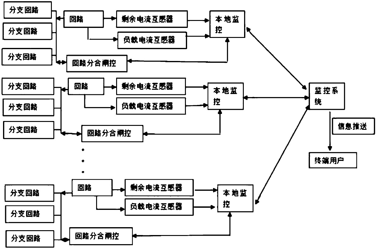
[0031] A distributed residual current measurement system, including several loops and a monitoring system, each loop is provided with several branch loops; each loop is equipped with

[0032] A residual current transformer, which is used to detect the residual current in the circuit;

[0033] a load current transformer, which is used to detect the load current in the loop;

[0034] Local monitoring, which interacts the real-time data of the residual current transformer and load current transformer with the background monitoring system, and controls the opening and closing of the circuit;

[0035] Opening and closing of the circuit, which controls the opening and clo...


PUM


Abstract

The invention provides a distributed residual current measuring system. The system comprises branch circuits, a circuit, a residual current transformer, a load current transformer, a local monitor, amonitoring system, a terminal user and a circuit switching-off and switching-on gate; the output end of the circuit is connected with the branch circuits, the residual current transformer and the loadcurrent transformer separately, and the residual current transformer and the output end of the load current transformer are connected with the input end of the local monitor separately; the local monitor and the monitoring system are in bidirectional connection, and the output end of the monitoring system is connected with the terminal user; the circuit switching-off and switching-on gate is in two-way connection with the branch circuits, and the circuit switching-off and switching-on gate is in two-way connection with the local monitor. The residual current of the distributed circuit is calculated, current alarm information of each circuit is judged, and the switching-off and switching-on functions of different circuits are remotely controlled, so that each branch circuit in the power supply circuit is detected and controlled. The system is convenient to use, good in safety, high in functionality and high in reliability.

Description

technical field [0001] The invention is a distributed residual current measurement system, which belongs to the technical field of circuit safety. Background technique [0002] The residual current measurement system is used in power supply networks for decentralized power supply in buildings, factories and mines. Three-phase residual current detectors and single-phase residual current detectors are used to form a network at the key ports of the power supply network to detect the residual current of each segmented power supply network line respectively. Current, the power supply switch at the next level of the power supply port uses the remote intelligent control opening and closing function module, controls the opening and closing of different circuits through the software system, calculates different currents, and then analyzes and judges to determine the maximum remaining current The power supply circuit of the system can give the alarm signal and line number, and can als...

Claims


Application Information

Patent Timeline
Patent Type & Authority Applications(China)
IPC IPC(8): G01R19/00G01R15/18G01R31/08
CPCG01R15/18G01R19/0092G01R31/085
Inventor 江正云
Owner SMART HLDG CO LTD
Why Eureka
Try Eureka