Novel new-energy charging pile device

A charging pile and new energy technology, which is applied in the field of new-type new energy charging pile devices, can solve the problems of casualties, single setting mode, and charging interruption, and achieve the effects of reducing potential safety hazards, high charging safety, and increasing simplicity

Inactive Publication Date: 2018-06-29
广州唐迈贸易有限公司
View PDF3 Cites 0 Cited by
  • Summary
  • Abstract
  • Description
  • Claims
  • Application Information

AI Technical Summary

Problems solved by technology

The charging pile is a supporting facility for new energy vehicles, and it is the carrier for charging new energy vehicles. However, the traditional charging pile setting mode is single, and the charging process only depends on the friction force when the charging terminal and the charging socket are plugged in to keep the state. If you accidentally touch the charging terminal or be affected by the pulling of the charging cable, it may cause the charging terminal to fall off, resulting in charging interruption. In addition, traditionally, the conductive sheet in the charging socket is generally placed relatively outside. This kind of conductive sheet is easy to be contacted by metal sheet or metal rod. Therefore, when a person who lacks safety awareness inserts the metal sheet or metal rod into the charging socket, an electric shock accident is likely to occur, which is likely to cause casualties. big security risk

Method used


Image

  • Novel new-energy charging pile device
  • Novel new-energy charging pile device
  • Novel new-energy charging pile device

Examples


Embodiment Construction

[0031] All features disclosed in this specification, or steps in all methods or processes disclosed, may be combined in any manner, except for mutually exclusive features and / or steps.

[0032] Any feature disclosed in this specification (including any appended claims, abstract and drawings), unless expressly stated otherwise, may be replaced by alternative features which are equivalent or serve a similar purpose. That is, unless expressly stated otherwise, each feature is one example only of a series of equivalent or similar features.

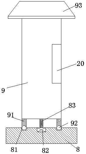
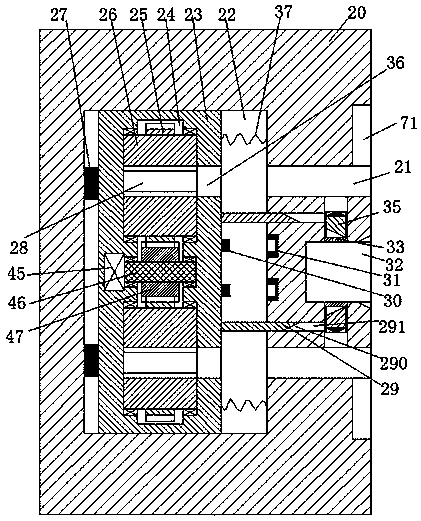
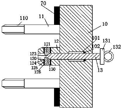
[0033] like Figure 1 to Figure 7 As shown, a new type of new energy charging pile device of the device of the present invention includes a charging pile body 9, a charging socket 20 disposed in the right end surface of the charging pile body 9, and a charging terminal 10 connected to a new energy vehicle. The top of the charging pile body 9 is fixed with a rainproof shed 94, the bottom of the charging pile body 9 is provided with a base 8, and...


PUM


Abstract

The invention discloses a novel new-energy charging pile device which comprises a charging pile body, a charging socket arranged inside the end face of the right side of the charging pile body, and acharging terminal connected with a new-energy vehicle, a sliding cavity is formed in the charging socket, a first insertion hole communicated with the outer end is formed in the right end wall of thesliding cavity, a sliding carrier is installed in the sliding cavity in a left-right sliding mode, a first tension spring abutting against the right end wall of the sliding cavity is arranged at the right end of the sliding carrier, an installing groove extending up and down is formed in the sliding carrier, rotating sleeves are vertically symmetrically and rotationally installed in the right endwall of the installing groove, spiral grooves connected left and right are formed in the rotating sleeves, a second insertion hole communicated with the sliding cavity is formed in the right end wallof the installing groove, a second toothed wheel is fixedly installed on the outer circle of each rotating sleeve, a first toothed wheel cooperatively connected with the second toothed wheel is rotationally installed between the two rotating sleeves through a rotating shaft, and the rotating shaft is connected with a second driver fixedly installed in the middle of the left end wall of the installing groove.

Description

technical field [0001] The invention relates to the field of new energy vehicles, in particular to a novel new energy charging pile device. Background technique [0002] New energy vehicles are gradually replacing traditional vehicles with many advantages such as energy saving, environmental protection and pollution-free, and are widely used. The charging pile is a supporting facility for new energy vehicles, and it is the carrier for charging new energy vehicles. However, the traditional setting mode of the charging pile is single. If you accidentally touch the charging terminal or be affected by the pulling of the charging cable, it may cause the charging terminal to fall off, resulting in charging interruption. In addition, traditionally, the conductive sheet in the charging socket is generally placed relatively outside. This kind of conductive sheet is easy to be contacted by metal sheet or metal rod. Therefore, when a person who lacks safety awareness inserts the metal...

Claims


Application Information

Patent Timeline
IPC IPC(8): B60L11/18
CPCB60L53/14B60L53/30B60L53/31Y02T10/70Y02T10/7072Y02T90/12Y02T90/14
Inventor 李俊敏
Owner 广州唐迈贸易有限公司
Why Eureka
Try Eureka