A kind of display panel, electronic equipment and preparation method of display panel

A display panel, one-sided technology, applied in circuits, electrical components, electrical solid-state devices, etc., can solve the problems of light leakage of the display panel, uneven brightness of the display image, affecting the display effect, etc., to achieve uniform screen brightness, better display effect, show uniform effect

Active Publication Date: 2020-02-18
BOE TECH GRP CO LTD
View PDF2 Cites 0 Cited by
  • Summary
  • Abstract
  • Description
  • Claims
  • Application Information

AI Technical Summary

Problems solved by technology

However, the biggest problem of the current COG process is that after the chip is attached to the chip at high temperature, due to the different thermal shrinkage coefficients of the preparation materials of the chip and the substrate, different shrinkages in the horizontal direction are produced, which in turn causes the substrate to warp (bend), and This warping (bending) phenomenon will cause stress on the substrate, thereby causing light leakage in the prepared display panel, or uneven brightness when displaying images, affecting the display effect

Method used


Image

  • A kind of display panel, electronic equipment and preparation method of display panel
  • A kind of display panel, electronic equipment and preparation method of display panel
  • A kind of display panel, electronic equipment and preparation method of display panel

Examples


Embodiment Construction

[0028] The present invention will be specifically described below in conjunction with the accompanying drawings.

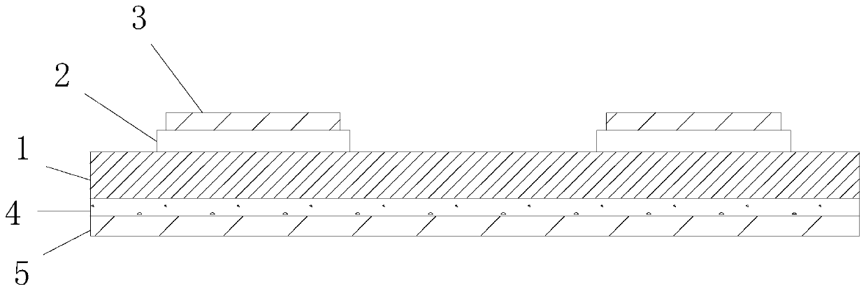
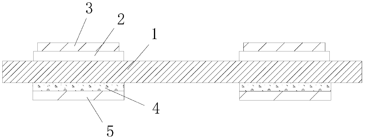
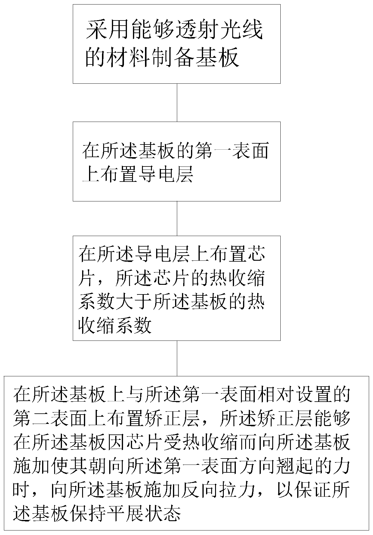
[0029] Such as figure 1 As shown, the embodiment of the present invention provides a display panel, including a substrate 1 capable of transmitting light, a thermally deformed portion is provided on the first surface of the substrate 1, and a correction layer is provided on the second surface of the substrate opposite to the first surface. 5. The rectifying layer 5 is used to balance the thermally deformable part and / or the force for deforming the substrate 1 generated by heating the substrate 1, so as to maintain the form of the substrate 1, that is, to maintain the substrate 1 in a flat state.

[0030] Specifically, a conductive layer 2 is provided on the first surface of the substrate 1, and the thermally deformed part is a chip 3 arranged on the conductive layer 2, wherein the chip 3 is made of a material whose thermal contraction coefficient is greater than t...


PUM


Abstract

The embodiment of the invention provides a display panel, electronic equipment and a preparation method of the display panel. The display panel comprises a base plate capable of transmitting light, wherein a thermal deformation part is arranged on one surface of the base plate, a correction layer is arranged on the other surface of the base plate and is configured to balance forces, for deformingthe base plate, produced when the thermal deformation part and / or the base plate are / is heated so as to maintain the form of the base plate. The display panel provided by the embodiment of the invention is simple in structure and is not deformed due to heating, and the display effect is not influenced.

Description

technical field [0001] The invention relates to the field of electronic display, in particular to a display panel, an electronic device with the display panel and a preparation method of the display panel. Background technique [0002] COG is the abbreviation of chip on glass, that is, the chip is directly bound on the glass. The COG process uses the flip chip (Flip Chip) conduction method to directly align the wafer (that is, the chip) with the electrodes on the glass substrate, and uses the Anisotropic Conductive Film (hereinafter referred to as ACF) material as the bonding interface. material, so that the electrodes in the vertical direction of the two combined objects are conducted. The current production process of the COG bonding process is carried out in an automated manner. [0003] The COG process is a commonly used circuit connection method for liquid crystal displays at present. Specifically, the chip is attached to the metal leads of the substrate through condu...

Claims


Application Information

Patent Timeline
Patent Type & Authority Patents(China)
IPC IPC(8): H01L23/498H01L21/60
CPCH01L23/49894H01L24/83H01L2224/83007
Inventor 赵伟利贾倩
Owner BOE TECH GRP CO LTD
Why Eureka
Try Eureka