Improved bridge equipment

A technology of equipment and bridges, which is applied in the field of improved bridge equipment, can solve the problems of large force applied by the contact strip, unstable power supply connection, and the contact strip is detached and clamped, etc., and achieves simple and convenient locking and unlocking operations, and simple and convenient locking operation , pull out the effect of convenient and labor-saving

Inactive Publication Date: 2018-07-03
朱顺华
View PDF0 Cites 0 Cited by
  • Summary
  • Abstract
  • Description
  • Claims
  • Application Information

AI Technical Summary

Problems solved by technology

[0002] At present, a large number of electrical facilities are used in the construction of bridges. The power supply of electrical facilities is mainly to insert the contact strips connected with the electrical facilities into the conductive grooves of the electrical sockets to tighten the electricity. Simple, but after the contact strip is inserted into the conductive groove, the contact strip can still be pulled out directly. When the contact strip is accidentally kicked and hits the cable connected between the contact strip and the electrical equipment, it will cause the contact strip to fall out of the conductive groove. Breaking away from the clamping will lead to a sudden power failure of the electrical equipment. Therefore, the existing clamping method has the risk of unstable power supply connection, which is likely to cause damage to the electrical equipment due to a sudden power failure. Moreover, the existing clamping method makes When the contact strip is pulled out, a large force needs to be applied, and it is more laborious to pull out

Method used


Image

  • Improved bridge equipment
  • Improved bridge equipment
  • Improved bridge equipment

Examples


Embodiment Construction

[0019] The preferred embodiments of the present invention will be described in detail below in conjunction with the accompanying drawings, so that the advantages and features of the present invention can be more easily understood by those skilled in the art, so as to define the protection scope of the present invention more clearly.

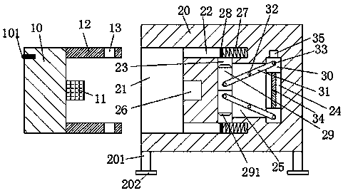
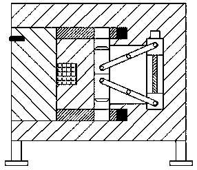
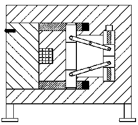
[0020] refer to Figure 1-4 The improved bridge equipment shown includes electrical connectors and electrical sockets connected to electrical facilities. The electrical connectors include a holding block 10, and two plugs are equally arranged at the front and rear ends of the right end surface of the holding block 10. Rod 12, the right end of each of the two insertion rods 12 is provided with a locking groove 13, the center of the right end surface of the holding block 10 is provided with a contact bar 11, the electrical socket includes a base 20, the A support column 201 is fixedly installed on the bottom surface of the base platform 20 , and a ...


PUM


Abstract

The invention discloses improved bridge equipment comprising an electrical plug and an electrical socket which are connected with an electrical facility. The electrical plug comprises a holding block.The front and rear ends of the right end surface of the holding block are equally provided with two inserting rods. The right end of each of two inserting rods is provided with a locking groove. Thecenter of the right end surface of the holding block is provided with a contact strip. The electrical socket comprises a base. The bottom end surface of the base is fixedly provided with support columns. The center of the bottom part of each support column is fixedly provided with an antiskid foot pad. The left end surface of the base is provided with a placing groove which is used for being connected with the holding block in a matching way, wherein the open end of the placing groove is leftward. The improved bridge equipment is simple in structure and great in power supply stability so thatthe application safety of the electrical facility in bridge construction can be increased, the whole device is safe and reliable to operate, locking and unlocking operation of the inserting rods and the contact strip is easy and convenient and unplugging of the electrical plug is convenient and labor-saving.

Description

technical field [0001] The invention relates to the field of bridges, in particular to an improved bridge device. Background technique [0002] At present, a large number of electrical facilities are used in the construction of bridges. The power supply of electrical facilities is mainly to insert the contact strips connected with the electrical facilities into the conductive grooves of the electrical sockets and clamp them to energize. Although this clamping method operates Simple, but after the contact strip is inserted into the conductive groove, the contact strip can still be pulled out directly. When the contact strip is accidentally kicked and hits the cable connected between the contact strip and the electrical equipment, it will cause the contact strip to fall out of the conductive groove. Breaking away from the clamping will lead to a sudden power failure of the electrical equipment. Therefore, the existing clamping method has the risk of unstable power supply conne...

Claims


Application Information

Patent Timeline
Patent Type & Authority Applications(China)
IPC IPC(8): H01R13/633H01R13/635H01R13/639H01R13/717
CPCH01R13/633H01R13/635H01R13/639H01R13/717
Inventor 朱顺华朱丹青
Owner 朱顺华
Why Eureka
Try Eureka