A gas distributor and a system comprising the gas distributor

A technology of gas distribution and system equipment, applied in chemical methods, chemical instruments and methods, chemical/physical processes, etc. that make liquids and gas media react, can solve the problems of dispersed bubble distribution and low gas holdup in towers, etc. Achieve the effects of reverse concentration difference, system operation flexibility and stable operation

Active Publication Date: 2021-06-04
CHINA NAT OFFSHORE OIL CORP +4
View PDF9 Cites 0 Cited by
  • Summary
  • Abstract
  • Description
  • Claims
  • Application Information

AI Technical Summary

Problems solved by technology

However, the distribution of bubbles in this sparger is too dispersed, resulting in low gas holdup inside the entire column, which is only suitable for reactions that do not require high gas holdup, and has certain limitations.

Method used


Image

  • A gas distributor and a system comprising the gas distributor
  • A gas distributor and a system comprising the gas distributor
  • A gas distributor and a system comprising the gas distributor

Examples


Embodiment 1

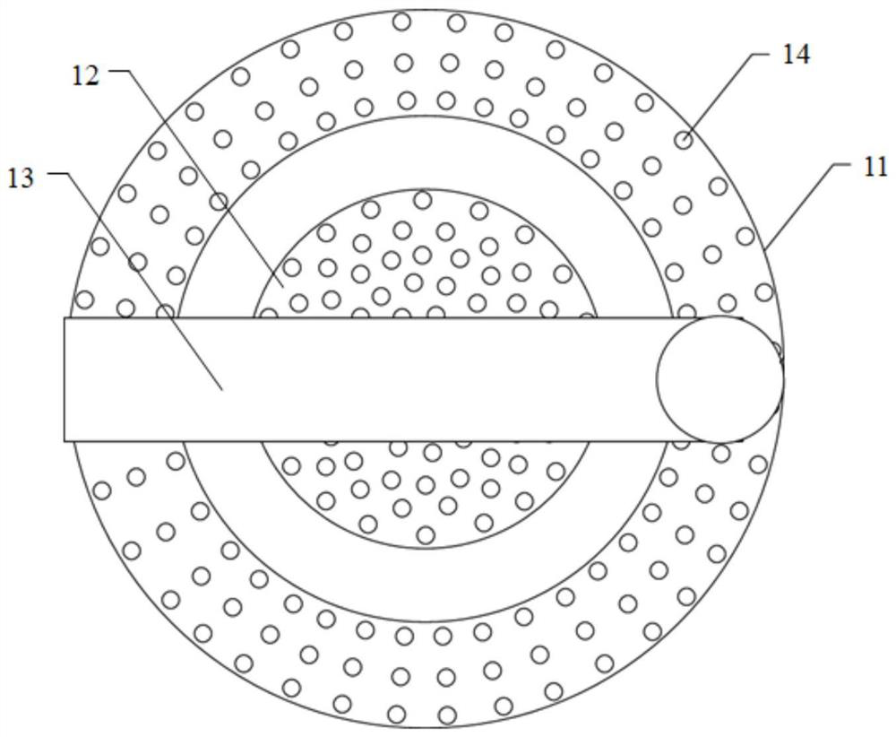
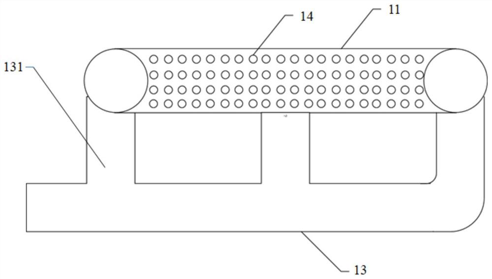
[0054] This embodiment provides a gas distributor (for a schematic diagram of its structure, refer to Figure 1a and Figure 1b ), the gas distributor includes an annular gas distribution pipe 11, a gas distribution box 12 located in the ring of the annular gas distribution pipe 11, and an inlet connected to the gas distribution pipe 11 and the gas distribution box 12 respectively. Trachea 13;

[0055] The air intake pipe 13 is respectively connected to the gas distribution pipe 11 and the gas distribution box 12 through the three air intake branches 131, so as to realize the fixing and air intake of the gas distribution pipe 11 and the gas distribution box 12;

[0056] Among the three air intake branches 131, one air intake branch 131 is connected to the gas distribution box 12, and the remaining two air intake branches 131 are connected to the radially opposite sides of the annular gas distribution pipe in pairs; the air intake pipe 13 Parallel to the plane where the annula...

Embodiment 2

[0060] Except for the following content, other content is identical with embodiment 1:

[0061] The air intake pipe 13 is respectively connected to the gas distribution pipe 11 and the gas distribution box 12 through the five air intake branches 131, so as to realize the fixing and air intake of the gas distribution pipe 11 and the gas distribution box 12;

[0062] Among the five air intake branches 131, one air intake branch 131 is connected to the gas distribution box 12, and the remaining four air intake branches 131 are connected to the radially opposite sides of the annular gas distribution pipe in pairs, and these four The connection ports between the two air intake branches 131 and the gas distribution pipe 11 are uniformly distributed on the gas distribution pipe; Air intake pipe 13 is vertical.

Embodiment 3

[0064] Except for the following content, other content is identical with embodiment 1:

[0065] On the gas distribution pipe 11, the air hole 14 close to the connection port of the gas distribution pipe 11 and the intake branch 131 has a small aperture, and is far away from the gas hole 14 at the connection port of the gas distribution pipe 11 and the intake branch 131. The aperture is large;

[0066] Preferably, on the gas distribution box 12, the air hole 14 close to the connection port of the gas distribution box 12 and the intake branch 131 has a small aperture, and is far away from the connection port of the gas distribution box 12 and the intake branch 131 The air holes 14 have a large aperture.


PUM


Abstract

The invention relates to a gas distributor and a system comprising the distributor. The gas distributor of the present invention includes an annular gas distribution pipe, a gas distribution box located in the ring of the annular gas distribution pipe, and an air inlet pipe connected to the gas distribution pipe and the gas distribution box respectively; The trachea is respectively connected to the gas distribution pipe and the gas distribution box through at least two divided air intake branches, so as to realize the fixing and air intake of the gas distribution pipe and the gas distribution box; the surfaces of the gas distribution pipe and the gas distribution box are uniform Has pores. The gas distributor of the invention has the advantages of simple structure, stable operation and good uniform distribution performance.

Description

technical field [0001] The invention relates to a gas distributor and a system including the gas distributor, in particular to a gas distributor, a bubble column including the gas distributor and a system. Background technique [0002] The production process in the chemical industry often involves reactions involving gas or liquid, which requires stirring components that can perform gas-liquid two-phase or gas-liquid-solid three-phase mixing. A gas distributor is a widely used component, especially widely used in multiphase fluidized reaction devices. [0003] At present, there are two types of gas distributors used in industry: plate gas distributor and tube gas distributor. One of their main functions is to make the reactants evenly distributed, speed up the reaction efficiency and shorten the reaction cycle. How to better control Pressure drop and flow rate to achieve better gas distribution are still the focus of research. [0004] CN 105944630 A discloses a gas distri...

Claims


Application Information

Patent Timeline
Patent Type & Authority Patents(China)
IPC IPC(8): B01J8/18B01J10/00
CPCB01J8/1827B01J8/1872B01J10/00
Inventor 王凯何霖傅送保王科侯章贵谭亚南王兴永程牧曦陈浩韩伟
Owner CHINA NAT OFFSHORE OIL CORP
Why Eureka
Try Eureka