Extensible optical fiber distribution frame

An optical fiber distribution frame and telescopic technology, which is applied in the field of power system, can solve the problems that the optical fiber distribution box cannot be pulled out smoothly, the operating space is narrow, and the redundancy of the optical cable is not enough, so as to improve the operation and maintenance work efficiency and safety. Reliable connection, the effect of reducing work pressure

Inactive Publication Date: 2018-07-13
ECONOMIC RES INST OF STATE GRID GANSU ELECTRIC POWER +2
View PDF4 Cites 0 Cited by
  • Summary
  • Abstract
  • Description
  • Claims
  • Application Information

AI Technical Summary

Problems solved by technology

However, in actual work, the optical cable at the back of the optical fiber distribution box often does not have enough margin during installation, resulting in the failure of the optical fiber distribution box to be pulled out smoothly. If the optical fiber distribution box is forcibly pulled out, the entire optical cable may be completely interrupted. This also allows the operation and maintenance personnel to only operate the fiber optic distribution box in a narrow enclosure
Due to the narrow operating space, it will also affect the operation accuracy of the operation and maintenance personnel. There may be phenomena such as the gaps on the fiber jumper not being aligned, and the jumper fiber being inserted into the wrong port, etc., which also cause certain hidden dangers to the safe operation of the optical communication system.

Method used


Image

  • Extensible optical fiber distribution frame
  • Extensible optical fiber distribution frame
  • Extensible optical fiber distribution frame

Examples


Embodiment Construction

[0018] The preferred embodiments of the present invention will be described below in conjunction with the accompanying drawings. It should be understood that the preferred embodiments described here are only used to illustrate and explain the present invention, and are not intended to limit the present invention.

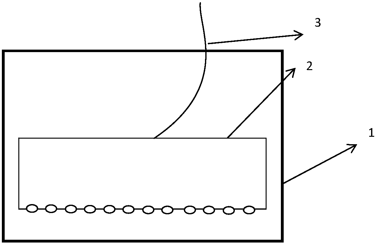
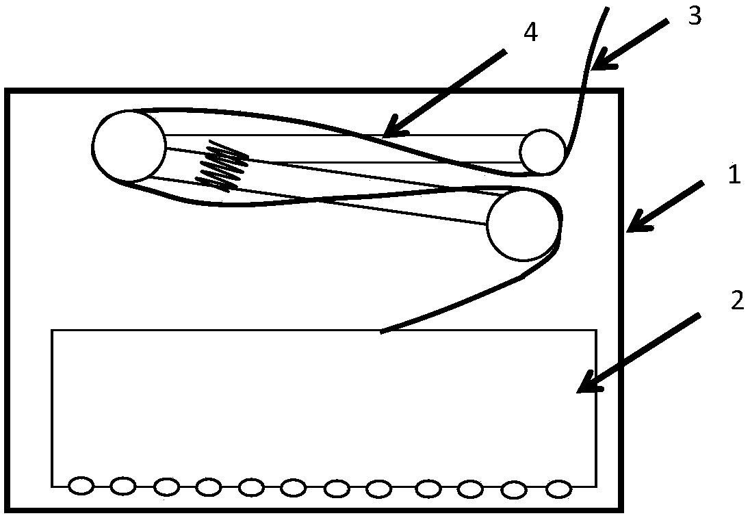
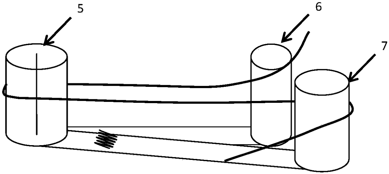
[0019] Such as Figure 2-5 As shown, a retractable optical fiber distribution frame, the distribution frame shell and the cabinet are fixed by screws, including the shell 1, the distribution box 2, the optical fiber 3 and the movable connector 4, and the inner side of the shell 1 is fixedly installed with a distribution frame. In the junction box 2, an active connector 4 is installed on the other side of the housing 1, and the optical fiber 3 passed out from the junction box 2 is wound on the active connector 4 and protrudes out of the housing. The movable connector includes cylinders 5, 6, 7, springs and connecting rods 8, 9, connecting rods 8 are connected between...


PUM


Abstract

The invention discloses an extensible optical fiber distribution frame. A shell of the extensible optical fiber distribution frame is fixed to a cabinet by the aid of screws. The extensible optical fiber distribution frame comprises the shell (1), a distribution box (2), an optical fiber (3) and movable connectors (4), and is characterized in that the distribution box (2) is fixedly mounted on oneinner side of the shell (1), the movable connectors (4) are mounted on the other inner side of the shell (1), and the optical fiber (3) which penetrates the distribution box (2) is wound on the movable connectors (4) and extends out of the shell. The extensible optical fiber distribution frame has the advantages of simple structure, low cost, safety, reliability and the like.

Description

technical field [0001] The invention belongs to the technical field of power systems, and in particular relates to a retractable optical fiber distribution frame. Background technique [0002] With the rapid development of the smart grid, the dependence on the optical communication network is also increasing. In the daily operation and maintenance of the optical communication network, a large number of fiber jumping operations need to be performed on the optical fiber distribution frame. Such as figure 1 As shown, in the power system, the optical fiber distribution frame is composed of the distribution frame shell 1, the distribution box 2 and the optical fiber 3. The distribution frame shell and the cabinet are fixed by screws, the distribution box is installed inside the shell, and the optical fiber is installed in the in the junction box. The distribution box is protected by the shell, so that the distribution box and the optical fiber are prevented from being disturbed...

Claims


Application Information

Patent Timeline
Patent Type & Authority Applications(China)
IPC IPC(8): G02B6/44
CPCG02B6/4452G02B6/4455
Inventor 平常王仕俊魏勇薛国斌王羿博
Owner ECONOMIC RES INST OF STATE GRID GANSU ELECTRIC POWER
Why Eureka
Try Eureka