

Electronic sphygmomanometer and control method for electronic sphygmomanometer
An electronic sphygmomanometer and control method technology, applied in medical science, sensors, diagnostic recording/measurement, etc., can solve problems such as difficulty in binding tightness, achieve the effect of ensuring consistency and avoiding detection errors
- Summary
- Abstract
- Description
- Claims
- Application Information
AI Technical Summary
Problems solved by technology
Method used
Image

Examples
Embodiment 1
[0055] Embodiment 1 provides an arm-type electronic sphygmomanometer, which can be used for blood pressure measurement.
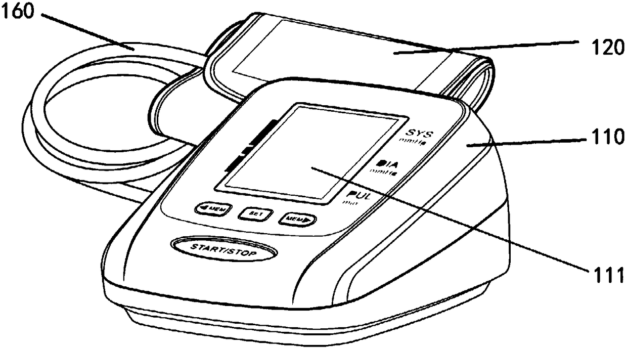
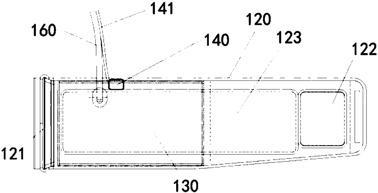
[0056] Please refer to figure 1 , 2a , 2b, 2c, the sphygmomanometer body 110 of the arm-type electronic sphygmomanometer has an air socket (not shown in the figure) for connecting the air path to the pulse sensing device, a display device 111, and some operation buttons and indicator lights. The wearing device is a cuff 120 . An air bag 130 as a pulse sensing device is installed in the cuff 120, which has an air joint (not shown). In this embodiment, the wearing tightness sensing device 140 is installed on the wearing device (cuff 120).
[0057] The fixing structure of the cuff 120 includes a metal ring 121, a magic hook surface 122 and a magic hair surface 123, that is, the fixing is realized by means of Velcro bonding.
[0058] In other embodiments, whether it is an arm-type electronic sphygmomanometer, a wrist-type electronic sphygmomanometer or a wa...
Embodiment 2
[0075] The second embodiment provides a wrist-type electronic sphygmomanometer, which can be used for blood pressure measurement.
[0076] Please refer to Figure 3-6 , the pulse sensing device of the electronic sphygmomanometer adopts an airbag 230, and the wearing device includes a wristband 220, and the airbag 230 is installed in the wristband 220. The airbag 230 has an air connection. The fixing structure includes an eyelet 221, a magic hook surface 222 and a magic hair surface 223.
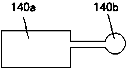
[0077] Wherein, the wearing tightness sensing device 240 adopts a force sensor, and the force sensor is arranged on the wristband 220, especially on the side of the wristband 220 close to the detection part, so that the force sensor can fit the detection part as closely as possible. . Of course, in other embodiments, the wearing tightness sensing device 240 may also adopt the gas container 140a and the pressure sensor 140b (pressure transducer) in the first embodiment.
[0078]In one exam...
Embodiment 3
[0082] The third embodiment provides a watch-type electronic sphygmomanometer, which can be used for blood pressure measurement.
[0083] Please refer to Figure 7-9 , the pulse sensing device of the watch-type electronic sphygmomanometer adopts an air bag 330, the body of the sphygmomanometer forms a watch head 310, and the wearing device includes a watch strap 320, and the air bag 330 is installed on the watch strap 320. Its fixing structure includes a buckle 321 and a buckle hole 322, and the buckle hole 322 has a plurality of hole positions for fastening in different positions.
[0084] Among them, please refer to Figure 9 , the wearing tightness sensing device 340 adopts a load cell, which is arranged on the side of the meter head 310 close to the detection site. Of course, in other embodiments, the wearing tightness sensing device 240 can also adopt the gas container 140a and the pressure sensor 140b (pressure transducer) in the first embodiment.
[0085] In one exam...
PUM
 Abstract
Description
Claims
Application Information