Computer-based 3D image imaging method and imaging system

An imaging system and imaging method technology, applied in the field of imaging systems, can solve the problems of not clear images, high price, distortion, etc., and achieve the effect of clear images and simple and cheap equipment

Active Publication Date: 2019-10-15
上海青燕和示科技有限公司
View PDF7 Cites 0 Cited by
  • Summary
  • Abstract
  • Description
  • Claims
  • Application Information

AI Technical Summary

Problems solved by technology

[0006] The technical problem to be solved by the present invention is to overcome the defects that 3D cameras in the prior art are expensive, often appear to be distorted, and the images are not clear enough, and provide a convenient and quick way to acquire 3D models.

Method used


Image

  • Computer-based 3D image imaging method and imaging system
  • Computer-based 3D image imaging method and imaging system

Examples


Embodiment 1

[0037] This embodiment provides an imaging system, and the imaging system includes a 3D lens and a computer. The computer is connected with the 3D lens and controls the shutter of the 3D lens. In this embodiment, the computer is an x86 computer, and the 3D lens may be an external or built-in lens of the x86 computer.

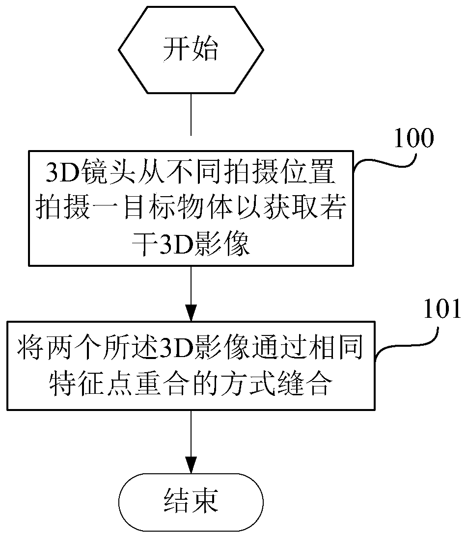
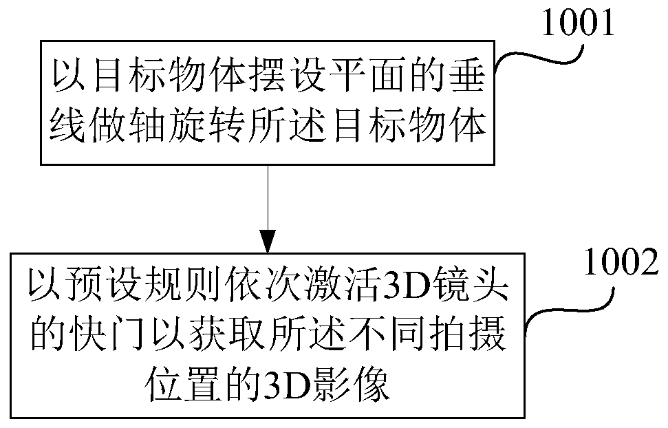
[0038] The 3D lens is used to shoot a target object from different shooting positions to obtain several 3D images, and the 3D images correspond to the shooting positions one by one.

[0039] For 3D images corresponding to any two adjacent shooting positions, the computer is used to identify feature points on the two 3D images, and stitch the two 3D images together by overlapping the same feature points.

[0040] The 3D lens includes an infrared beam emitter, an infrared receiver and a camera, the infrared beam emitter and the infrared receiver are used to generate the structural layer of the 3D image, and the camera is used to generate the 3D image pixel layer....

Embodiment 2

[0056] This embodiment is basically the same as Embodiment 1, the only difference is:

[0057] The computer of this embodiment can also realize a specific image stitching function:

[0058] For a target 3D image, the computer is used to select a feature point in the target 3D image, and obtain the distance from the feature point to the axis of the fixed axis and the target angle, wherein the target angle is the feature point The angle between the line connecting the projection point of the axis and the plane where the 3D camera and the axis are located.

[0059] The computer is also used to determine the feature points in the next 3D image in the next 3D image of the target 3D image through the rotation angle of the disk, the distance from the feature point to the axis and the included angle of the target The position of the target 3D image and the next 3D image of the target 3D image are stitched in such a way that the feature points overlap.

[0060] On the same level, the...

Embodiment 3

[0067] This embodiment is basically the same as Embodiment 1, the only difference is:

[0068] Each 3D image includes a pixel layer and a structure layer, and for 3D images corresponding to any two adjacent shooting positions, the computer is used to identify at least 3 peak points on the structure layers of the two 3D images;

[0069] The computer is also used to sew the structural layers of the two 3D images by overlapping the same peak points, the peak points include convex points and concave points, and the number of overlapping peak points of the two 3D images is at least 3, and attach two pixel layers of the 3D image to the stitched 3D image.

[0070] Using the imaging system of this embodiment, the stitching method in the 3D image imaging method of this embodiment specifically includes:

[0071] identifying at least 3 peak points on the structural layers of both said 3D images;

[0072] Stitching the structural layers of the two 3D images by overlapping the same peak ...


PUM


Abstract

The invention discloses a 3D imaging method and an imaging system based on a computer. The imaging system comprises a 3D lens and a computer. The 3D imaging method comprises the steps as follows: the3D lens shoots a target object from different shooting positions to acquire a plurality of 3D images, wherein the 3D images are corresponding to the shooting positions; feature points on the two 3D images separately corresponding to any two adjacent shooting positions are recognized, and the two 3D images are seamed by the way of stacking the same feature points. The 3D imaging method and imagingsystem based on the computer provided by the invention can acquire a 3D model, and is convenient and rapid. Furthermore, the image is clearer, and the implementation equipment is simple and cheap.

Description

technical field [0001] The invention relates to a computer-based 3D image imaging method and imaging system. Background technique [0002] A 3D camera is a camera made with a 3D lens. It usually has more than two camera lenses with a distance close to that of the human eye, and can capture different images of the same scene similar to what the human eye sees. Holographic 3D has more than 5 lenses on the disk, and the same image can be viewed in all directions through dot grating imaging or rhombus grating holographic imaging, as if you are on the scene. [0003] The first 3D camera So far the 3D revolution has all revolved around Hollywood blockbusters and major sports events. With the advent of 3D cameras, this technology is one step closer to home users. After the launch of this camera, we will be able to use 3D lenses to capture every memorable moment in life, such as a child's first step, college graduation celebration and so on. [0004] 3D cameras usually have more ...

Claims


Application Information

Patent Timeline
Patent Type & Authority Patents(China)
IPC IPC(8): H04N13/275H04N13/207
Inventor 孙燕生
Owner 上海青燕和示科技有限公司
Why Eureka
Try Eureka